1 Overview
With the vigorous development of new energy vehicles, people have put forward more and more demands for new energy electric vehicles. As the most important part of new energy electric vehicles, the performance of motors has been greatly challenged. How to make the motor respond faster, have better power, and higher efficiency, how to quickly develop high-performance motor assemblies to meet customer needs, occupy their own place in the fierce market, and have become major motors and motor control The problem to be solved urgently by device manufacturers. As a local high-tech enterprise, Hengrun Technology has been committed to the research and development of HIL (Hardware in the loop) test equipment for motors, which will help manufacturers of motors and motor controllers to quickly develop high-performance products to meet market demand.
2. Test requirements
The motor HIL test equipment is mainly for testing the motor controller. It has the advantages of safety, speed, and repeatability, and can quickly test the functions of the motor controller. The core part of the motor HIL test equipment is mainly composed of hardware and models. The hardware is used to form an electrical circuit with the motor controller hardware. The model mainly includes an inverter model and a motor body model, which is used to form a logic circuit with the control algorithm of the motor controller. The combination of hardware and model provides a complete simulation test platform for the motor controller. The article mainly introduces the inverter model in the motor HIL test equipment in detail.
3. Inverter modeling
The function of the inverter is to modulate the DC bus voltage into AC voltage. The AC voltage generates a rotating magnetic field to drive the permanent magnet rotor (permanent magnet synchronous motor) or the rotor coil (AC asynchronous motor) to rotate. According to the modulation method, it is divided into SPWM, SAPWM, SVPWM, etc. This article does not expand the modulation method, mainly focuses on the simulation modeling of a single IGBT and diode, and studies the voltage and current changes when the IGBT or diode is turned on and off.
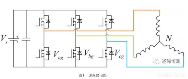
There are generally two modeling methods for inverters. One method is to treat IGBTs and diodes as ideal switches. When the switch is opened, both ends of the switch are completely disconnected. When the switch is closed, both ends of the switch are equivalent to wire connections. Another method is to treat the IGBT or diode as a variable impedance. When the switch is on, the IGBT or diode is equivalent to a capacitor, and when the switch is off, the IGBT or diode is equivalent to an inductance. The first method corresponds to the ideal switch model, and the second method corresponds to the advanced inverter model that this article will focus on.
â— Ideal switch model The ideal switch model modeling method is extremely simple. The basic model unit of the ideal switch model is a bridge arm. When the upper bridge arm is closed, the intermediate point voltage is equal to the DC bus positive voltage. When the lower bridge arm is closed, the intermediate point voltage Equal to the negative voltage of the DC bus, the upper and lower arms must be opened and the other closed.

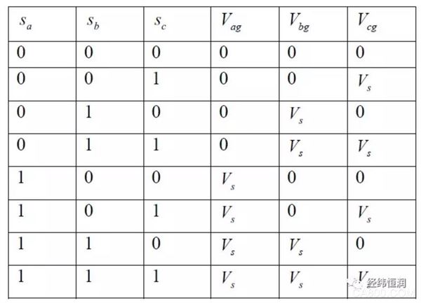
The advantage of this modeling method is that the algorithm is simple, and a simple look-up table can be used. It can reflect the influence of the switch on the three-phase voltage from a certain level. At present, many motor HIL test equipment use this method for modeling, but the modeling method is also There are many disadvantages:
? There is no modeling for a single IGBT, but for the switching state of a bridge arm (two IGBTs), which means that some algorithms such as half-bridge control cannot be implemented, which means that a single IGBT or diode cannot be faulted simulation.
? The diode conduction is not considered. There are two possibilities for switch conduction, IGBT conduction or diode conduction. This modeling method only considers IGBT conduction.
It takes time to turn on and off the IGBT, which is also the time difference that the dead zone control needs to consider. In this modeling method, the IGBT turns on and off immediately and does not meet the IGBT response characteristics.
? This modeling method cannot directly realize current feedback from the circuit principle. The negative current can only be calculated by means of negative torque, thereby indirectly achieving energy recovery, which is different from the real system.
Based on the above reasons, Hengrun has developed an advanced inverter model.
â— Advanced inverter model The principle of advanced inverter model modeling is to treat an IGBT or diode as a variable impedance. When it is off, the IGBT or diode is equivalent to a capacitor, and when it is on, the IGBT or diode is equivalent to an inductance. If the modeling is directly carried out in this way, discontinuity of voltage and current will be generated when the switch is switched on and off. Due to the fast switching frequency of the inverter, this modeling method is likely to cause the system to diverge. To solve this problem, IGBT or diode can be used as a constant current source and connected in parallel with a fixed impedance, as shown in Figure 2. The size of the constant current source depends on whether the IGBT or diode is turned on. The size of the impedance depends on the impedance of the simulated capacitor and inductor.
The following demonstrates the working process of the IGBT model based on a circuit in which a resistor and IGBT are connected in series. Figure 3 shows the voltage and current changes at both ends of the IGBT during the opening and closing of the switch. When the IGBT drive signal is high, the IGBT is turned on and the current flowing through the IGBT gradually increases until it equals E/R, and the voltage across the IGBT gradually decreases until it reaches zero. When the IGBT drive signal is at a low level, the IGBT is turned off, and the current flowing through the IGBT gradually decreases until it is equal to 0, and the voltage across the IGBT gradually increases until the power supply voltage E.
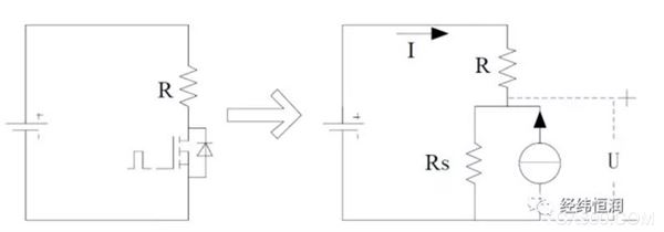
Figure 2. Demonstration circuit of switch closing process
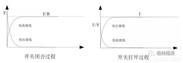
Figure 3. Voltage and current change process during switch opening and closing
The circuit shown in Figure 1 is equivalent by the equivalent relationship in Figure 2:
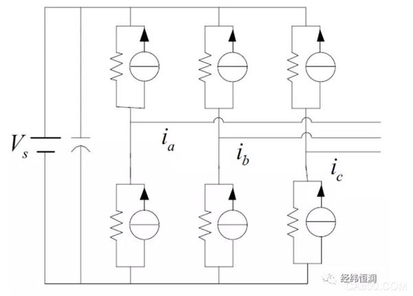
Figure 4. Inverter equivalent circuit
From the inverter equivalent circuit and Kirchhoff’s law, the calculation formulas for the three-phase voltage and bus current can be derived, and the final inverter model is as follows:
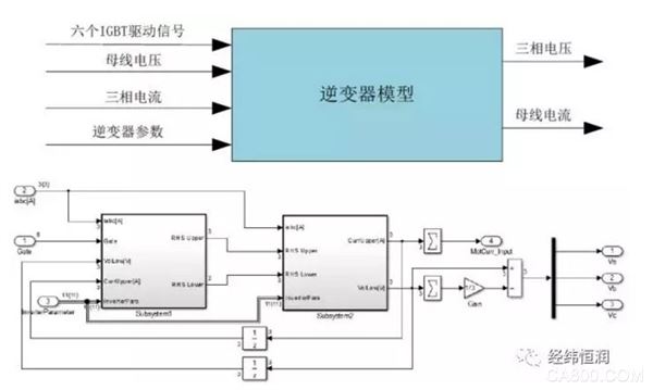
Figure 5. Inverter model
The following demonstrates how the inverter works when all six IGBTs are turned off, which cannot be simulated by the ideal switch model. (Assuming the motor speed is 100rad/s, the inverter bus voltage is 580V)
If the motor is idling at a speed of 100rad/s, an induced electromotive force will be generated, and the induced electromotive force will generate an induced current. Figure 7 shows the three-phase induced current calculated by the motor model.
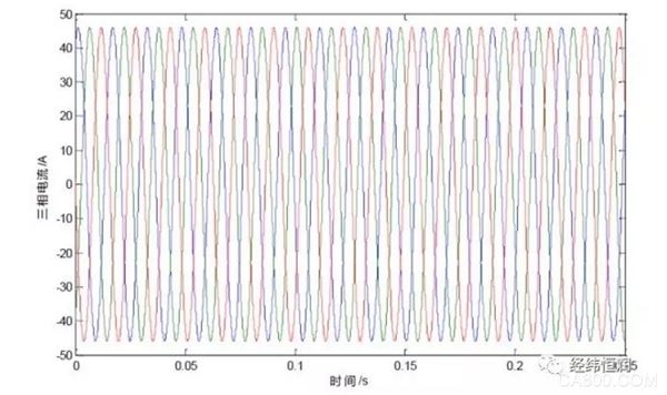
Figure 6. Motor three-phase current
The three-phase induced current flows into the inverter, and the three-phase voltage is calculated. It can be seen from the figure that the peak value of the three-phase voltage is about 28V, and the induced electromotive force is

The two are basically equal, and the reason for not being completely equal is that there is a partial voltage drop on the motor coil.
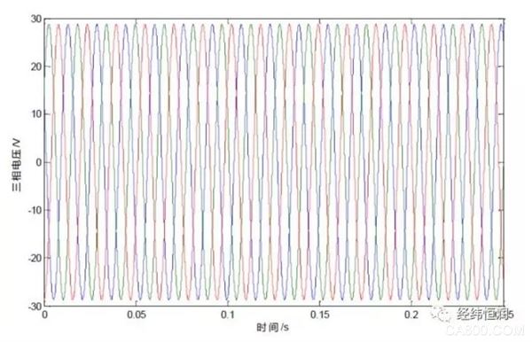
Figure 7. Motor three-phase voltage
The final output torque of the motor is 0, as shown in Figure 8, which is consistent with the actual situation. The advanced inverter model makes up for the shortcomings of the ideal switch model, and can more realistically reproduce the opening and closing processes of IGBTs and diodes; can simulate the influence of induced electromotive force on motors and inverters; can directly realize energy recovery from circuit principles .
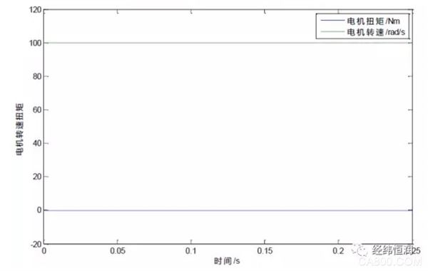
Figure 8. Motor speed and torque
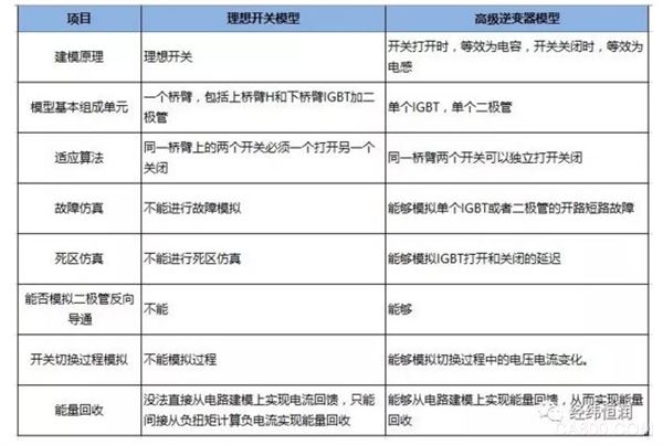
â— Comparison of advantages and disadvantages
4. Conclusion
The motor controller HIL test equipment can be carried out in a laboratory environment. The equipment has high reliability, good integration, easy to use and configure, and easy to maintain and expand. At the same time, equipped with powerful automated test functions can greatly improve test quality and efficiency. .

Hengrun Technology, 6th Floor, Block D, Zhizhen Building, No. 7 Zhichun Road, Haidian District, Beijing
URL:
a thing that joins together two parts of sth, two vehicles or two pieces of equipment.
Custom Coupling,Coupling Of Encoders,Useful Coupling,Latest Coupling
Yuheng Optics Co., Ltd.(Changchun) , https://www.yhenoptics.com