Good thermal management is becoming more and more important when designing these electronic products, including LED systems.
LEDs constantly emit heat, and the lampshade becomes smaller and smaller. Brightness and power consumption continue to increase, but LEDs that are closely aligned (car front and rear lights) are not equipped with a corresponding cooling fan. Therefore, reliability and performance are bound to be affected. If the LED exceeds the critical junction temperature, a problem occurs: the LED light is dimmed. If the temperature continues to be too high, the life of the LED will be shortened and then prematurely scrapped. The average life of LED lights on a car is several thousand hours, and premature retirement will give manufacturers additional warranty costs.
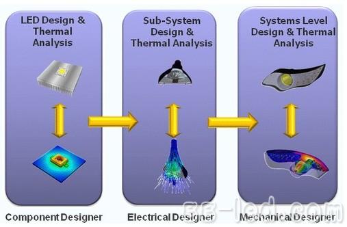
Excellent thermal management depends on good thermal design. As shown in Figure 1, the LED component is the first step in the design process. Component designers use thermal analysis software and test equipment to analyze the material and structure of the component to ensure that the heat generated by the junction can easily be dissipated through the LED component layer. The subsystem designer will arrange the LED components in an array, add heat sinks and other cooling devices, and then analyze the product again. They may adjust the separation distance between the LED components or add additional cooling to ensure that the LED does not exceed the critical temperature. The final step is usually done by a mechanical design engineer using a mechanical computer-aided design system. The designer places the aligned LEDs into a lampshade (such as a car headlight) and uses advanced computational fluid dynamics (CFD) software for thermal analysis. .

figure 1
Design blank
So where is the problem? The industry has been using excellent CFD thermal analysis software for many years. Products such as FloTHERM are fast, accurate, and easy to use, and require no external experts to complete the analysis. The problem is that the accuracy of the software analysis results depends on the accuracy of the input component model. If the input component model is inaccurate, the software's results will only mislead the designer, no matter how perfect the analysis process.
But the key is the typical LED data sheet provided by the supplier, which only shows its total power consumption (such as maximum forward current and voltage), and the individual thermal resistance between the “junction†and some reference points (such as solder joints). There is no information on how heat passes through the layers in the package and there is no thermal path/obstacle description that can be used to define the thermal resistance and heat capacity of each layer.
What is the problem with this? Typically, thermal management experts estimate the internal structure of the package and create a thermal model that describes the thermal resistance and heat capacity of each layer and structure. As long as this model has a deviation of a few percent, it will lead to inaccurate analysis, and there is no way to verify or judge the quality of such a thermal model.
So fundamentally, there is still a gap in the design of the cooling system. In all aspects of product development (components, subsystems, and the entire system), thermal analysis must not be less, but good thermal analysis results are only possible if the component thermal model is good. Without knowing the internal structure of the packaged components, we cannot define or verify the accuracy of the model, and usually the component suppliers will not disclose intellectual property in this area.
Fill in the gap
The solution is to create a “bridge†between hardware test/measurement and thermal analysis by defining and verifying a simplified thermal model of the components shown in Figure 2. Existing hardware is capable of measuring the thermal characteristics of a component. With cutting-edge software, these measurements can be translated into simplified thermal and thermal capacity networks that we can read in thermal analysis software.
For example, by connecting Mentor's T3Ster hardware to the component under test, the transient temperature change of the junction can be measured, accurate to 0.01 degrees Celsius, regardless of the heating or cooling process of the component. In the process of heat dissipation from the junction to the surrounding environment, more than 10,000 data points can be collected in one minute to describe the transient change of junction temperature, and the transient change characteristics of the junction temperature represent the layers of the component. Thermal resistance and heat capacity. With this data, the analysis software can automatically generate LED simplified thermal models. An accurate and effective model was born.

Hardware testing and measurement can be used to create or verify LEDs to simplify thermal mode
LED suppliers are designed to use this technology to measure thermal performance and optimize it before measuring and creating a thermal model for the customer. Subsystem and system developers can use it to verify the thermal model obtained from the supplier or create the model themselves without the supplier providing the model. The reliability of electronic equipment is small, and the design responsibility usually falls on the original manufacturer. The quality assurance and recycling problems will directly affect their profit and loss. Therefore, they need to confirm that their product design is no problem.


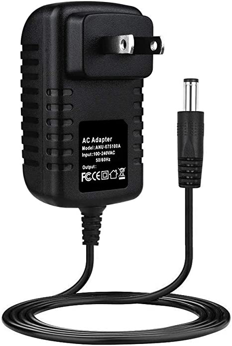
AC wall 5V 2A power adapter with multiple tips works for many small 5V electronics. Like Scanner, Router, Bluetooth speaker, Foscam Wireless IP Camera, CCTV camera, USB hub, bluetooth GPS Receiver, tv box, tablets, Baby Monitor, Graco Swing, Home Phone System, VoIP Telephone Routers, Serato DJ Controller, DVR, ADSL Cat, External battery, hubs, switches, Led Strip, String Lights, vibrator, Raspberry pi 3 Raspberry Pi A/A+/B/B+ Raspberry Pi Zero and more 5V devices. (5V ONLY)
Worldwide Input: 110-240V; Output: 5V 1000mA, 1.5A, 1.75A, 5V 1A, 5V 500mA, 5V 2.1A, Max 10W. DC Tip Polarity: Central Positive(+). Please read manual carefully before using 5vdc power supply.
Design-safeguard features against incorrect voltage, short circuit, internal overheating and overloading. This 5v Ac power supply charger is made from quality material to ensure the long lifetime. Power your 5v electronics perfectly and replaces lots of 5 volt power chargers
Package include: 1 x High Quality 5V 2A AC DC Power Adapter, 1 Set x Tips
5V Switching wall charger 6V Switching wall charger 9V Switching wall charger 12V Switching wall charger 15V Switching wall charger 19V Switching wall charger 24V Switching wall charger 36V Switching wall charger 48V Switching wall charger
Shenzhen Waweis Technology Co., Ltd. , https://www.waweispowerasdapter.com