Application of BIST on Embedded Microprocessor Core on SoC Chip
introduction
With the continuous development of technology, the manufacturing process and design level of integrated circuits have been rapidly improved, and designers can integrate very complex functions into silicon wafers. The system of multi-chip on the PCB is integrated into a chip. This chip is a system-on-chip, SoC (System on Chip). The characteristics of the SoC chip are mainly two aspects: the first is its high complexity, and the second is the extensive use of reusable IP (Intellectual Property) modules. In the past, chip designs often focused on module design for a specific function, such as compression/decompression, wireless modules, network modules, and so on. The function of a SoC chip may be the sum of multiple independent modules. In addition, the manufacture of chips needs to undergo processes such as chemistry, metallurgy, optics, etc., in which physical defects may be introduced to cause them to malfunction. Therefore, testing of the chip becomes an indispensable part. Design ForTest (DFT) considers the need for future testing during the design phase of the chip, making chip testing easier and more efficient, and reducing test costs. An SoC contains a variety of reusable functional IP cores, of which the embedded microprocessor core is a key part, most of which are embedded with one or more microprocessor cores for best performance. Therefore, research on the issue of microprocessor core testability is becoming more and more urgent.
1 Traditional test methods
Before the 1970s and 1980s, when integrated circuits were still small-scale circuits, most of the tests were done by adding incentives and detecting corresponding methods. This method is still feasible in the case of a small circuit scale and a low frequency, but as the size of the integrated circuit grows, the content of functional verification increases, or when an asynchronous excitation signal is required, such a test method has limitations. In order to improve the test coverage of the fault point, an automatic vector generation (ATPG) tool has appeared. Using the ATPG algorithm and a powerful computer, you can detect as many points of failure as possible. As the size of the chip grows, the ratio of the number of gates to the number of pins becomes too large. The method of testing only through the input/output pins can hardly be applied any more, so another scanning-based test technique has emerged. - DFT. But when the scan chain is long and the number is large, the single chip test time is still very long. At the same time, the price of advanced test instruments has risen sharply, making BIST (Built-In Self-Test), the in-chip test method, inevitable.
2 Several commonly used BIST methods and their advantages and disadvantages
On-chip testing is an effective means to save time and cost of chip testing. The testing speed of external testing is increasing by 12% per year, while the speed of on-chip chips is increasing by 30% per year. This contradiction further promotes the application of BIST. . Due to the wide variety of IPs within the SoC chip, different BIST test methods are used for different IP cores. The advantages of using BIST technology are: reducing test costs, improving error coverage, reducing test time, facilitating customer service and independent testing. Currently, BIST test methods mainly include MemBIST and LogicBIST.
2.1 MemBIST
MemBIST is a test method for embedded chip memory to test whether the memory works normally. Inside the chip is a BISTController that generates the various modes and expected results of the memory test and compares the read and expected results of the memory. MemBIST can be divided into RAMBIST and ROMBIST. At present, the more commonly used memory BIST algorithm has the March algorithm and its variants. The tools commonly used in the industry are Mentor Graphics' MBIST Architecture.
2.1.1 RAMBIST test structure
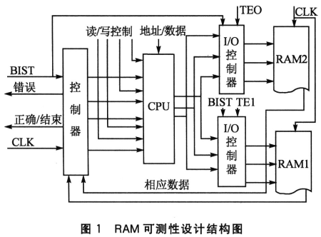
Both the data cache and the instruction cache implemented in RAM use the normal BIST method. Because the two RAMs are identical in structure, in order to reduce area consumption, only one set of test circuits is used. During the test, external signals TE0 and TE1 respectively control whether RAM1 and RAM2 are in the test state, and TE0 and TE1 cannot be valid at the same time. The test circuit structure is shown in Figure 1.

Under the control of the external input signal BIST, the controller generates read/write control signals, access addresses and test codes, compresses and analyzes the corresponding data of the RAM, and compares the obtained feature values ​​with the standard feature values ​​stored in the chip. The test results are reported through two I/O ports, and a preliminary fault diagnosis function is also implemented. When a fault is found, the TAP controller can move the erroneous address out of the chip to provide further troubleshooting and repair.
2.1.2 ROMBIST test structure
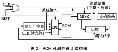
The cyclic redundancy check (CRC) circuit is usually used to implement the ROM test. Although the test result is very reliable, the information needs to be read bit by bit, and the access to the ROM is 32 bits at a time. If this method is used, it is required. A buffer mechanism and the speed will be slow. In this case, parallel data compression in the RAM test is still used, the fault coverage rate can be achieved, and the test circuit is simpler than the CRC circuit. The test circuit is shown in Figure 2.

The BIST test signal is input by the TDT port of the TAP controller. It is the enable signal of the entire test circuit. After the test process is triggered, it is completely completed inside the circuit. After the end, the test result is reported through an I/O port. The multi-input register (MISR) is used as the data register of the TAP controller, and is set to the initial state during test initialization.
2.2 LogicBIST
The LogicBIST method uses the internal vector generator to generate test vectors one by one, applies them to the circuit under test, and then digitally compresses and discriminates to generate an authentication code, which is compared with the expected value.
LogicBIST is commonly used to test random logic circuits. Pseudo-random test pattern generators are generally used to generate input test patterns for internal device mechanisms; MISR is used as an output signal generator. Due to the structure of the MI-SR and the inherent characteristics of the authentication code of the multi-input sequence, this is a many-to-one mapping relationship. Different input sequences may generate the same authentication code after passing through the MISR, which is called alias.
The LogicBIST test only gives the results of whether the chip can pass the test. Once the chip can't pass the test, how do you determine where the fault point inside the chip is? This is the diagnostic work, but LogicBIST's support for fault diagnosis is too weak. If a chip fails to pass, the wrong authentication code is very It is difficult to determine where the fault is. Sometimes a combination of multiple fault points inside the chip causes the authentication code to be the correct one. This is called a leak test. The probability it produces is very small, and there are algorithms to minimize the probability of a leak test occurring. One of the methods is to input the correct sequence and a single mapping with the correct authentication code. Other errors must be obtained by the wrong authentication code. This method requires specific analysis of the MISR, PRRG, and CUT to change the structure or PRPG generation order.
Conclusion
This paper introduces the research status of the core testability technology of embedded microprocessor on SoC. It introduces the technology of embedding relevant functional circuits in the circuit to provide self-test function to reduce the device test to automatic test equipment (ATE). The degree of dependence. BIST technology can be self-tested and can solve problems that many circuits cannot directly test (because they have no external pins).
It is foreseeable that even the most advanced ATE will not be able to fully test the fastest circuits in the near future, which is one of the reasons for adopting BIST. But BIST also has some shortcomings, such as extra circuitry that takes up valuable area, extra pins, and potential test blind spots. BIST technology is becoming an alternative to high-priced ATE, but it is not yet fully capable of replacing ATE, they will coexist for a long time to come.
AC Series LED Grow Bars,LED Light Bar ,LED Tube Light ,LED Lights Online
LED Bulb Light Co., Ltd. , http://www.nbgrowlights.com