The importance of data does not need to be described, the key is how to use it.
This article refers to the address: http://
In the past two or three years, in the various interpretations of the Internet of Vehicles, similar words can often be seen: when the car is connected to the Internet, it is no longer an island of information, and there are various possibilities. Therefore, the killer application has become a point of competition for everyone.
From the point of view of the realization of the Internet of Vehicles, to make the vehicle no longer an "island", having the networking function is only the beginning. To achieve "unlimited possibilities", we must first solve two problems: who is connected with it, and then after the connection what. Regarding these two issues, every car manufacturer and service provider has its own ideas.
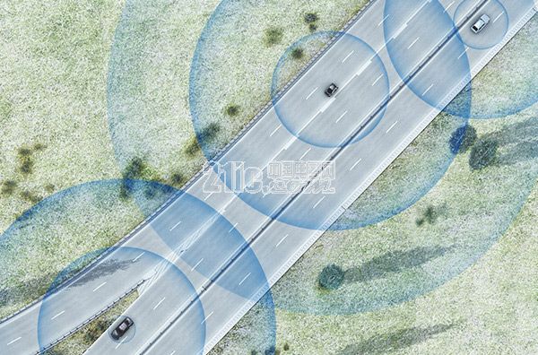
In the trip to Audi in Munich last week, in addition to a close contact with VR glasses, Car Cloud has learned that he is a little dizzy 3D, and also learned some progress of Audi's current Car-to-X communication project. . Audi will join the Car-to-X service in the Audi Connect service this year, first on the A4/A5 and Q7. From the middle of this year, Audi will begin to collect information and establish a database. When the database reaches a certain scale, Audi will release data for the first time at the end of the year. The service will be launched first in Germany, and the time to launch the service in China has not yet been mentioned.
3 data sharing functions
In the Car-to-X technology shown this time, the cloud is the first station to connect, and it is also the distribution center of data. Different data will have different flow directions. After the data is collected on the vehicle side, it is uploaded to the cloud through the in-vehicle network and then transmitted to other Audi vehicles through the cloud. There are currently three types of data and development features that Audi is collecting:
1. Preset the driving mode by traffic sign information
The traffic sign information is identified by the car camera and uploaded to the cloud. Data uploaded to the cloud needs to be verified before it is released. The standard of verification is the number of cars that upload this information. Only after a sufficient number of cars have uploaded this information will it be verified and then shared into other vehicles and navigation systems.
This way of updating information is more meaningful for autonomous driving and the current predictive ACC system. At that time, the vehicle will preset the driving mode according to various traffic information in the system, such as changing the speed of the vehicle in advance for the speed limit information.
2. Collect and share vehicle hazard information
The current hazard information includes two types of information: one is that an Audi brand car has an accident or malfunction; the other is that the surrounding environment may affect safe driving, such as slippery roads or reduced visibility due to heavy fog and heavy rain.
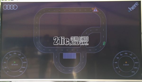
Vehicle failure information collected by the demonstration system in real time. The former activates the eCall emergency call system on the vehicle, or the vehicle automatically issues an accident report when the airbag is activated. For the latter, the specific impact information needs to be evaluated. And verification, such as the data received by the rainwater and light sensors on the vehicle, and the operating mode of the wiper to evaluate the visibility outside the vehicle, the verified dangerous information will be shared to other vehicles through the cloud.
3. On-street parking space information sharing
When the car is driving, the vehicle will use the ultrasonic sensor or camera to identify the free parking space and parking space occupancy information on the roadside and upload it to the cloud.
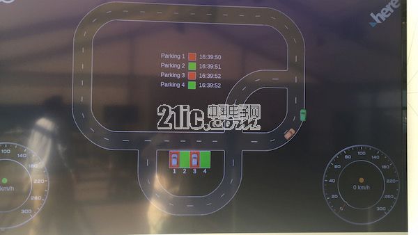
The parking space information collected by the demonstration system in real time The sharing of the parking space information includes two aspects. On the one hand, the system analyzes the parameters such as the position, steering angle and speed of the vehicle to determine whether the vehicle is entering and Leave the parking space and if it is found, it will automatically send a report to the cloud server. This type of instant information can be shared in real time in other Audi vehicles.
On the other hand, based on historical data and real-time data, a statistical model is established, and then free space parking data that may exist in the current time can be calculated as a guide information for the driver to find a parking space.
Among them, not only the sensors on the vehicle are required to receive and analyze the data in time, but also the data foundation is large enough. How to cross the boundaries of the brand is a problem that every car company is considering. Mercedes-Benz mentioned that Car-to-X will be open to other brands, but did not propose specific measures and implementation time.
2 functional verification methods: model car and PCC
On the cloud platform, a large amount of data can be obtained every second. Who should connect this data? Audi gives two different verification methods. One is to verify the technology and projects under development through the model car, and the other is through a project called PCC (Personal Company Car) in Audi, which is based on the actual vehicle and the technology that has been mass-produced. authenticating.
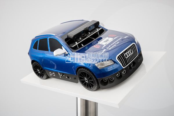
Audi Q5 1:8 model car This is the model car that Audi is now testing. The model car is modeled on Q5 with a ratio of 1:8 and is driven by an electric motor with a top speed of 40 km/h. The car is equipped with two cameras - one monocular and one stereo, with ten ultrasonic sensors - five in front, three in the rear, and one on each side, to detect lane lines, traffic signs, obstacles and parking. Bit and so on. There is also an acceleration sensor that records the direction of the model car. In the car, there is a high-speed computer with a quad-core processor. The structure of this microcomputer is the same as that used on the Audi self-driving car. The data on the car can be passed to the cloud in the background in real time via Wi-Fi.
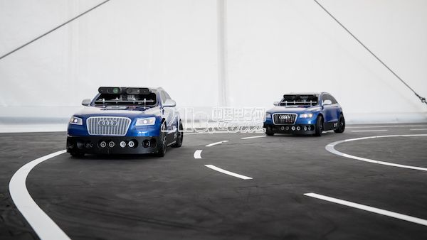
The model car is undergoing a functional demonstration on site, and the model car demonstrates three functions. In terms of presentation effects, the uploading and distribution of information is highly real-time, and for temporary "bursty" situations - obstacle avoidance workers entering the site to detect vehicle obstacle avoidance functions can also identify and bypass in advance. However, this model car approach is more suitable for the mechanism and principle of verification technology, and the investigation of the information transmission speed, emergencies and other factors in the real environment depends on the test in the real environment. The PCC project is generated for this purpose.
Starting in mid-2015, Audi began testing PCC projects. As of the middle of this year, 70 Audi managers have joined the project to test connectivity and data sharing capabilities. According to Audi engineers, Germany has strict regulations on personal privacy data protection, so Audi has set up a team to test this function, and for those involved in the test, on vacation or other data that does not want to be collected. At the time, you can apply for abort test in advance. Audi said that all collected data is anonymous.
Product Description
SPD Surge Protective Device,Lightning Surge Protector
Surge Protection Device (SPD)
It is a device used to limiting instant surge voltage and discharge surge current, it at least including a non-linear component.
Surge protective Device Model Selection
With the impact of international information flow, the rapid development of microelectronic science and technology, communication, computer and automatic control technology, make the building start to go for high quality, high functional area, formed a new building style-intelligent building. As inside the intelligent building there are lot of information system, <<Building lightning protection design norm>> GB50057-94(2002 vision)(hereafter brief as <<lightning protection norm>>) put forward the relative requirement to install the surge protective device, to ensure the information system safely and stable running.
SPD essentially is a equipotential connection material, its model selection is according to the different lightning protection area, different lightning electromagnetic pulse critical and different equipotential connection position, decide which kind of SPD used in the area, to achieve the equipotential connection with the common earth electrode. Our statement will based on SPD's maximum discharge current Imax, continuous operating voltage Uc, protection voltage Up, alarm mode etc.
As per << Lightning Protection Norm>> item 6.4.4 stipulation "SPD must can withstand the expected lightning current flow and should confirm to the additional two requirements: the maximum clamp voltage during surge across, capable to extinguish the power frequency follow-on current after lightning current across." That is the value of SPD's max. clamp voltage add its induction voltage of two ends should be same with the system's basic insulation level and the equipment allowed max. surge voltage.
SPD for Power Supply System Series Selection Guide
The installation of SPD at each lightning protection zone, according to the standard of low voltage electrical appearance, make classification of electrical equipment in accordance with the over voltage category, its insulation withstand impulse voltage level can determine the selection of SPD. According to the standard of low voltage electrical appearance, make classification of electrical equipment in accordance with the over voltage category as signal level, loading level, distribution and control level, power supply level. Its insulation withstand impulse voltage level are:1500V,2500V,4000V,6000V. As per to the protected equipment installation position different and the different lightning current of different lightning protection zone, to determine the installation position of SPD for power supply and the break-over capacity.
The installation distance between each level SPD should not more than 10m, the distance between SPD and protected equipment should as short as possible, not more than 10m. If due to limitation of installation position, can't guarantee the installation distance, then need to install decoupling component between each level SPD, make the after class SPD can be protected by the prior class SPD. In the low voltage power supply system, connecting an inductor can achieve the decoupling purpose.
SPD for power supply system specification selection principle
Max. continuous operating voltage: bigger than protected equipment, the system's max. continuous operating voltage.
TT System: Uc≥1.55Uo (Uo is low voltage system to null line voltage)
TN System: Uc≥1.15Uo
IT System: Uc≥1.15Uo(Uo is low voltage system to line voltage)
Voltage Protection Level: less than the insulation withstand impulse voltage of protected equipment
Rated discharge current: determined as per to the lightning situation of the position installed and lightning protection zone.
SP1 Series
Normal Working Conditions
-Altitude not exceed 2000m
-Ambient air temperature:
Normal range: -5ºC~+40ºC
Extend range: -40ºC~+80ºC
-Relative Humidity: 30% - 90% under indoor temperature condition
- At the place without obviously shaking and shock vibration
- Non-explosion danger medium, non-corrosion gas and dust ( including conductive dust)
Classification
-As per Nominal Discharge Current:
5,10,20,30,40,60KA(8/20µs)
- As per Maximum continuous operating voltage:
275V,320V,385V,420V,440V,460V
- As per to poles
1P,1P+N,2P,3P,3P+N,4P
- As per auxiliary functions:
a. With remote signal output ( remote alarm function)
b. Without remote signal output
Selection Principle
- The continuous applied voltage on the two terminals of SPD should not more than the maximum continuous operating voltage Uc value;
- The voltage protection level Up of SPD should less than the maximum impulse withstand voltage of the protected equipment;
- As per to the different earthing system and protection mode to select the specification accordingly;
Product Features
1, built-in over-current overheating, temperature control circuit technology.
2, the module design, easy installation, online replacement.
3, low leakage current, fast response time, low residual voltage.
4, alarm indication device, green (normal) v red (fault).
| Model/Technical Parameters | WR-B60 | WR-B80 | WR-B100 | WR-B120 | WR-B150 |
| Rated Operating Voltage Un (V ~) | 220V 380V | 220V 380V | 220V 380V | 220V 380V | 220V 380V |
| Maximum Continuous Operating Voltage Uc (V ~) kV | 385V 420V | 385V 420V | 385V 420V | 385V 420V | 385V 420V |
| Voltage Protection Level Up (V ~) kV | ≤1.8≤2.2 | ≤2.4≤2.5 | ≤2.5≤3.2 | ≤3.4≤3.7 | ≤4.0≤4.5 |
|
Maximum Discharge Current Imax(8/μ20μs)kA |
60 | 80 | 100 | 120 | 150 |
|
Nominal Discharge Current In(8/μ20μs)kA |
30 | 40 | 60 | 80 | 100 |
| Response Time | <25 | <100 | |||
| L/N(mm²)The Cross Section Of L/N Line | 16,25 | 16,25 | 16,25 | 16,25 | 25,35 |
| PE (mm²)The Cross Section Of PE Line | 16,25 | 25,35 | 25,35 | 25,35 | 35 |
| Fuse or Switch (A) | 63A | 63A | 63A,100A | 63A,100A | 63A,125A |
| The Line Section of Communication and Alarm (mm²) | ≥ 1.5 | ||||
|
Operating Environment-C |
(-40ºC~-+85ºC) | ||||
| Relative humidity 25 ºC | ≤95% | ||||
| installation | Standard Rail35mm | ||||
| Material of Outer Covering | Fiber Glass Reinforced Plastic | ||||
Surge Protector SPD,Surge Protection Device SPD,SPD
Wenzhou Korlen Electric Appliances Co., Ltd. , https://www.zjaccontactor.com