1 Introduction
The corridor automatic lighting, which integrates sound control, light control and touch control, makes the public corridor lights in public places and residential areas not light during the daytime, and the nighttime sounds bright, after waiting for a few minutes (time adjustable) It is automatically turned off afterwards, which is convenient and saves electricity. Mechanical manual switches are commonly used in public buildings and public corridors in residential areas. Due to various reasons, many light bulbs are often brightened, which results in short lamp life and waste of electricity, causing economic losses for the state, units and individuals. In addition, due to frequent switching or other human factors, the damage rate of the wall switch is high, which not only increases the maintenance amount, wastes funds, but also easily causes accidents. Therefore, it is quite necessary to design and develop an energy-saving automatic switch with three-control incandescent lamp with novel circuit, safe power saving, simple structure and convenient installation. In the past, most of the voice-activated switches were designed with analog electronic technology. There are many discrete components and they are not reliable. Nowadays, the single-chip technology is quite mature. You can use the single-chip microcomputer to design an intelligent voice-activated switch. After the circuit is designed, use software programming to realize it. Function, flexible and easy to modify. At present, the average service life of many voice-activated switches is not long, mainly because the circuit is frequently switched, and the starting current is very large, which causes the power component thyristor to be damaged due to overload. In this paper, the switching voltage zero-crossing protection technology can eliminate the large current impact of the incandescent lamp on the instant of opening, effectively prevent the current overload when the thyristor element starts, greatly extend the service life of the switch, and can protect the bulb. effect.
2 corridor automatic lighting overview
Use sound sensors, light sensors and touch control technology to control the lighting and extinguishing of the light. Sound, light and touch three-control lighting is a simple and practical lighting control circuit, which can be controlled by sound and light, or by human touch. Install the device in corridors, corridors, etc. When the light is dark at night, when the person walks or makes a sound, the light will automatically light up and delay automatically for a few minutes (time adjustable). During the day, if the electrode pad is touched, the light is also triggered to illuminate.
3 Scheme argumentation
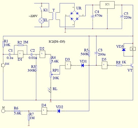
The schematic diagram of the sound, light and touch three control lighting is shown in Figure 1. The whole control circuit is composed of power, sound control, light control, touch control, delay, relay drive and other circuit parts.
After the AC 220V voltage is stepped down by the power transformer T, the rectifier bridge stack UR rectification, C4 filter and IC1 voltage regulation, 5V DC voltage is generated at both ends of C5, which is supplied to the relay and the whole control circuit.

Figure 1 Schematic diagram of the sound, light and touch three control lighting circuit
After the power is turned on, the entire control circuit operates in the standby state, and the non-gate D5 outputs a low level, so that the transistor VT is turned off, the normally open contact of the relay K is not attracted, and the illumination lamp EL is not lit.
When someone approaches the light or emits a sound, the microphone BM converts the sound signal into an electrical signal, and the electrical signal is amplified by the AC linear amplifier formed by the non-gate D1, and then outputted to the high level after being inverted by the non-gate D2. The output of the non-gate D3 becomes low level, the diode VDl is turned on, the output end of the non-gate D5 becomes high level, the transistor VT is saturated and turned on, the normally open contact K1 of the relay K is attracted, and the illumination EL Glowing.
During the day, even if someone has footsteps or other sounds, there will be no high level of input to the input terminal of the door D3, because the photoresistor RL is illuminated and the resistance value becomes smaller, and the input end of the non-door D3 is always Low level, the output terminal also maintains a high level, the diode VD1 and the transistor VT are both in an off state, and the illumination lamp EL is not lit. At night, the resistance value of the photoresistor RL becomes larger. At this time, if the microphone BM picks up the sound signal, a high level is applied to the input terminal of the non-gate D3, so that the diode VD1 and the transistor VT are turned on, and the relay K is The normally open contact is closed and the illumination EL is illuminated.
Regardless of day and night, as long as the electrode piece M is touched by hand, the human body sensing signal will cause the input end of the NOT gate D4 to become a high level, and its output terminal will become a low level, and the diode VD2 will be turned on. The input end of D5 becomes low level, the output end becomes high level, the transistor VT is saturated and turned on, K1 is closed, and the illumination lamp EL is lit.
When the diode VD1 or VD2 is turned on, the capacitor C3 is quickly charged by VD1 or VD2, and the input of the non-gate D5 is immediately low; when the output of the NOT gate D3 or D4 changes from low level to high level ( Then, at the same time, it becomes low level. When VD1 or VD2 is turned off, capacitor C3 is slowly discharged through resistor R5, so that the input terminal of the non-gate D5 is still maintained at a low level for a period of time, and the illumination lamp EL will not be extinguished immediately. Until the end of C3 discharge, the D5 input becomes high, the output becomes low, the transistor VT is turned off, the relay K is released, and the illumination EL is extinguished.
Component selection:
IC1 selects LM7805 type three-terminal integrated voltage regulator;
IC2 selects CD4069 type six-gate digital integrated circuit.
VT selects 9013 or 8050 silicon NPN medium power transistor, which requires current amplification factor β>100.
The UR is either a 2A, 50V rectifier bridge stack or a bridge with four 1N5401 silicon rectifier diodes.
VD1-VD3 selects 1N4148 switching diode for use.
C11 and C2 select CL11-63V type polyester capacitors; C3-C5 selects CD11-16V type electrolytic capacitors.
RL selects MG45-13 or MG45-33 type photoresistor. The remaining resistors use RTX-1/4W carbon film resistors.
RPl selects the WH7-A vertical trimmer potentiometer.
BM uses CM-18W high sensitivity electret microphone.
T selects 220V/6V, low quality finished power transformer, which requires no long-term no-load operation but not hot.
4 corridor automatic lighting works
4.1 Principle of voice-activated automatic lighting
4.1.1 Schematic diagram of voice-activated automatic lighting

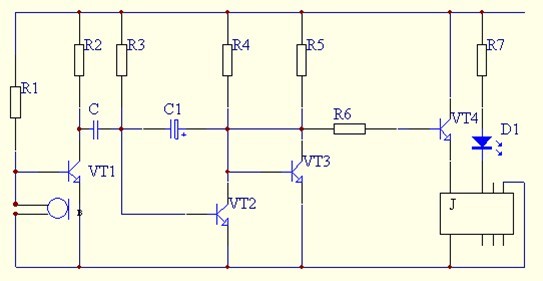
Figure 2 voice control circuit

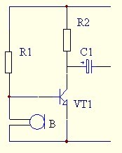
Figure 3 sound induction, amplification circuit

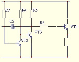
Figure 4 monostable circuit
4.1.2 Principle analysis of voice-activated automatic lighting
2 is a voice control circuit portion, which is composed of the sound sensing and amplifying circuit of FIG. 3 and the monostable circuit of FIG. In Figure 4, the transistors VT2, VT3 and their resistors and capacitors form a monostable circuit. Resistor R3 provides the base current for transistor VT2; the base current of transistor VT3 is derived from the collector resistance R4 of transistor VT2. The collector of the triode VT2 is directly coupled to the base of the triode VT3; the coupling between the collector of the triode VT3 and the base of the triode VT2 is performed by the capacitor C2. Resistor R4 is the collector load of transistor VT2, and the collector load of transistor VT3 is resistor R5. The characteristic of a monostable circuit is that it has only one steady state. When there is no signal input, the circuit selects reasonable R3 to stabilize the triode VT2 in saturation state, and its collector voltage is about 0.3V or less. This stabilizes the transistor VT3 in the off state. This is the steady state of the monostable circuit. When a negative pulse reaches the base of the transistor VT2 through C1, the transistor VT2 begins to turn off, its collector current decreases, and the collector voltage rises; after direct coupling, the base voltage of the transistor VT3 rises, the transistor VT3 When it starts to conduct, its collector voltage drops; the coupling of capacitor C2 causes the base voltage of transistor VT2 to drop further (although the negative pulse no longer exists), forming a positive feedback and quickly reaching a new one. status. At this time, the triode VT2 is turned off, and the triode VT3 is saturated and turned on. This is the transient state of the monostable circuit. The transient state of a monostable circuit is not sustainable. During the transient state, capacitor C2 discharges through resistor R3. As the discharge progresses, the base voltage of transistor VT2 gradually increases. When it reaches 0.5V or higher, transistor VT2 begins to conduct, and positive feedback occurs again. The entire circuit quickly returns to VT2 saturation conduction, VT3 cut-off steady state. Capacitor C2 determines the hold-up time of the circuit through the discharge process of resistor R3. According to the calculation, this time t = 0.7 × R3 × C2. In this circuit, the resistance R3 is 510KΩ, and the capacitance C2 is 47μF, so t≈17s. Changing the parameters of the resistor R3 or the capacitor C2 according to this formula can lengthen or shorten the delay time of the circuit. After the circuit is restored, capacitor C2 is charged through the resistor R5 and the emitter junction of transistor VT2. The circuit can receive the next trigger after charging is complete. B in the circuit is an electret microphone that converts the sound signal into an electrical signal. The electric signal converted by the electret microphone is weak. Only the amplifier composed of the transistor VT1 amplifies the weak signal to trigger the monostable circuit. When the negative pulse in the amplified signal acts on the base of the transistor VT2, the monostable circuit can be flipped.
In the steady state process of the circuit, the monostable circuit transistor VT2 is turned on, and the transistor VT3 is turned off. The collector of the triode VT3 is at a high level, and the triode VT4 connected thereto is a PNP type triode, so the triode VT4 is not turned on, and the relay does not operate. Once the external sound triggers the circuit, the base of the triode VT2 in the monostable circuit is turned off by the action of the negative pulse, and the monostable circuit is in the transient state. At this time, the transistor VT3 is turned on, and its collector voltage is lowered, so that the triode VT4 connected thereto is turned on, the relay is pulled in, and the LED circuit is turned on to light up.