Take the following assumptions:
— Both sides of the groove can be parallel, convergent (small mouth and small bottom), or dispersed (small mouth large).
— For discrete grooves, if the minimum width exceeds 0.25 mm, the depth exceeds 1.5 mm, and the bottom width is greater than or equal to 1 mm, it is considered to be an air gap, and the creepage distance is measured along the contour of the groove (see Case 8).
– For any angle of angle less than 80°, it is assumed that a short length of 1 mm (0.25 mm for anti-soil deposition protection) is bridged on the insulating material and the position of the line is the most unfavourable The location (see case 3).
– If the width of the groove opening is greater than or equal to 1 mm (0.25 mm for anti-fouling protection), the creepage distance is measured along the contour of this groove. (See case 2).
— For creeping components, measure creepage distances and clearances when they are in the most unfavourable static position.
— When calculating the total clearance, any air gap of less than 1 mm in width (0.25 mm for anti-fouling protection) is negligible.
 S3409
S3409
Case: There are grooves with parallel or convergent edges on the path under consideration, the width is less than 1 mm, and the depth is not.
Rule: Creepage distance and clearance are measured directly across the groove as shown.
Situation 1
 S3410
S3410
Case: There are grooves with parallel sides on the path considered, the width is greater than or equal to 1 mm, and the depth is not.
Rule: The creepage distance is measured by the “dotted line†in the figure, and the clearance is measured directly across the groove.
Situation 2
 S3411
S3411
Situation: There is a V-shaped groove on the path considered, the internal angle is less than 80 degrees and the width is greater than 1 mm.
Rule: The clearance is measured directly across the groove. The creepage distance is calculated according to the contour of the groove, but 1 mm is used at the bottom of the groove (
For the case of anti-fouling deposition protection, take 0.25mm) for short connection.
Situation 3
 S3412
S3412
Situation: There are ridged objects on the path considered.
Rule: The creepage distance is measured along the contour of the ridge, which is the shortest spatial path across the top of the ridge.
Situation 4
 S3413
S3413
Situation: There are non-closed objects on the path considered, and the groove width on both sides is less than 1mm
(For the case of anti-fouling deposition protection, take 0.25mm).
Rule: Creepage distance and clearance are taken as the line of sight path shown.
Situation 5
 S3414
S3414
Situation: There are non-tightly bound objects on the path considered, and the groove width on each side is greater than or equal to 1 mm.
Rule: The clearance is taken as the line of sight path shown. The creepage path follows the contour of the slot.
Situation 6
 S3415
S3415
Situation: There are non-tightly bound objects on the path considered, and the groove width on one side is greater than or equal to 1 mm.
The groove width on the other side is less than 1 mm.
Rule: Clearance and creepage path are shown in the figure.
Situation 7
 S3417
S3417
Situation: There are diverging edge grooves on the path under consideration, the depth is more than 1.5 mm, the width at the narrowest point is greater than 0.25 mm, and the width at the bottom is more than 1 mm.
Rule: The clearance is shown by the line of sight in the figure, and the creepage distance is along the contour of the groove.
Case 3 applies at the same time if the angle is less than 80° at the inner corner.
Situation 8
 S3418
S3418
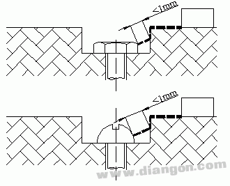
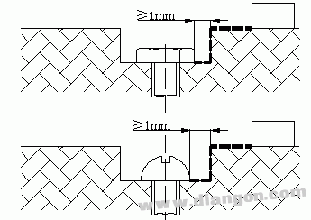
If the gap between the concave wall and the bolt head is too small, it is ignored.
Situation 9
 S3419
S3419
For a sufficiently wide recess, the value of the gap between the bolt head and the wall should be taken into account.
Passive Stylus Pen,Custom Stylus Pen,Stylus Pen For Surface,Smart Stylus Pen
Shenzhen Ruidian Technology CO., Ltd , https://www.wisonens.com