Dynamic car weighing is the weighing platform that the car passes through a certain width at a certain speed. The weight of each axle of the car is measured by the weighing table, and then the total weight of the car is accumulated. The weighing process is a strong real-time process that requires the microcontroller to collect data from each axis of the car and quickly calculate its weight. If the speed of the microcontroller is too slow or the program design is unreasonable, it will bring stability and reliability to the instrument. At present, many smart meter software adopts the front/backstage system design. The whole application is an infinite loop. The background program loops to call the corresponding function to complete the corresponding operation, and the interrupt service program handles the asynchronous event. This traditional programming idea has obvious shortcomings. The entire application is an organic whole, making real-time application design and expansion difficult, time-critical events are difficult to achieve fast and efficient processing, serial processing of events makes resources not well utilized. Porting embedded operating systems in smart meters can better solve the above problems, and make software development work standardized, easy to test, modular programming and shorten development cycle. Of course, the RTOS itself needs to occupy a certain amount of resources. With the development of semiconductor technology, the performance of the device continues to rise and the cost continues to decrease, making the cost consumed by the RTOS no longer important. The automotive dynamic weighing instrument is transplanted with an embedded operating system, which enhances system stability and reliability in practical applications.
2 System overall scheme The vehicle dynamic weighing instrument is mainly composed of data acquisition module, data processing module, display module, data communication module, external memory and external watchdog, as shown in Figure 1. The data acquisition module is responsible for amplifying, filtering, and converting the weight signal detected by the load cell into a digital signal for transmission to the CPU; the CPU is responsible for analyzing and processing the communication and weight signals with each peripheral device, and transmitting the processed weight signal to the Display module and communication module; display module is responsible for display of weight signal: communication module is responsible for sending weight signal to upper computer; external memory stores instrument parameters: button is used to set and modify instrument parameters; external watchdog is used to improve instrument Anti-interference ability, enhance the stability of the instrument.
This article refers to the address: http://
3 hardware circuit design
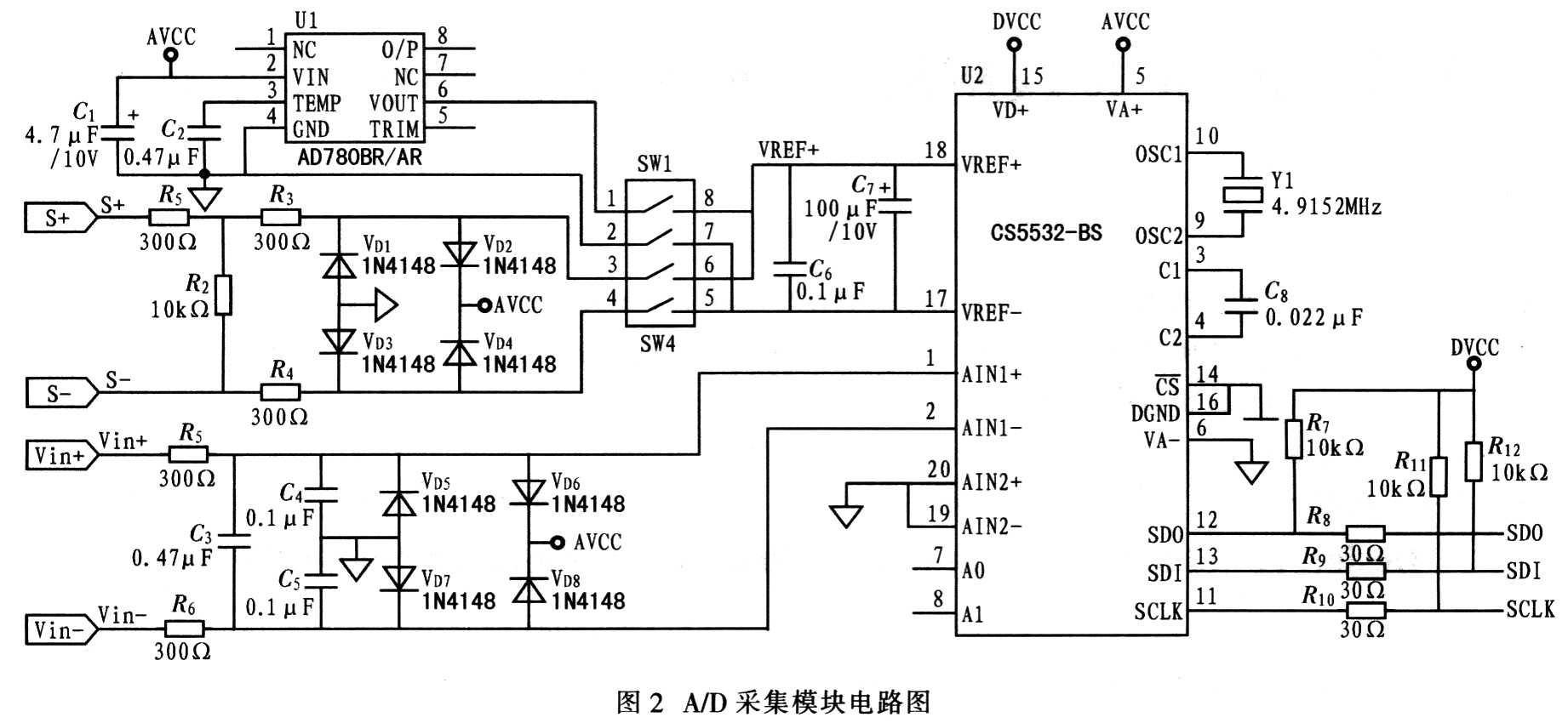
3.1 Data Acquisition Module Because the weighing instrument needs high precision, an external A/D converter is used, and CS5532 is selected. The device is a multi-channel analog/digital converter with very low noise introduced by Cirrus Logic of the United States. It integrates amplification and amplification due to its charge balance technology and extremely low noise programmable gain chopper-stabilized measurement amplifier. Filtering for up to 24-bit resolution with high dynamic range and flexible power configuration options makes the device ideal for dynamic weighing. Its reference voltage is provided by a dedicated reference voltage device AD780. The circuit is shown in Figure 2.

3.2 Microprocessor and external memory The microprocessor is the core of the system, and its performance directly determines the accuracy, stability and reliability of the weighing system. Based on the requirements of precision and real-time performance of the automotive dynamic weighing instrument, PHILIPS' P89C668 single-chip microcomputer was selected. It has the following characteristics:
1 chip with 8 KB RAM, 64 KB Flash memory, which can be programmed in parallel or serially (ISP). In actual molding products, the user program can be upgraded by ISP; 2 the device is in 6 clock cycles. Execute one instruction within the traditional 80C51 twice; in each machine cycle, the speed is up to 20 MHz in 6 clock cycles (equivalent to 40 MHz performance); 3 the device has four 8-bit I/O ports, 3 16-bit timer/event counter, multi-interrupt source, 4 preferred stages, nestable interrupt structure, an enhanced UART and on-chip oscillator and sequential circuitry; these resources provide sufficient I/O for system hardware design The port provides sufficient program storage space for the implementation of software complex functions and future program extensions. It provides sufficient data storage space for the weight data sampling, filtering and weighing algorithm implementation. The ISP function can be used to implement the product. Software upgrade.
The external memory uses ATMEL's AT24C512 device, an electrically erasable nonvolatile EEPROM memory with 64 KB of memory and an I2C interface, providing storage for setup and calibration parameters.
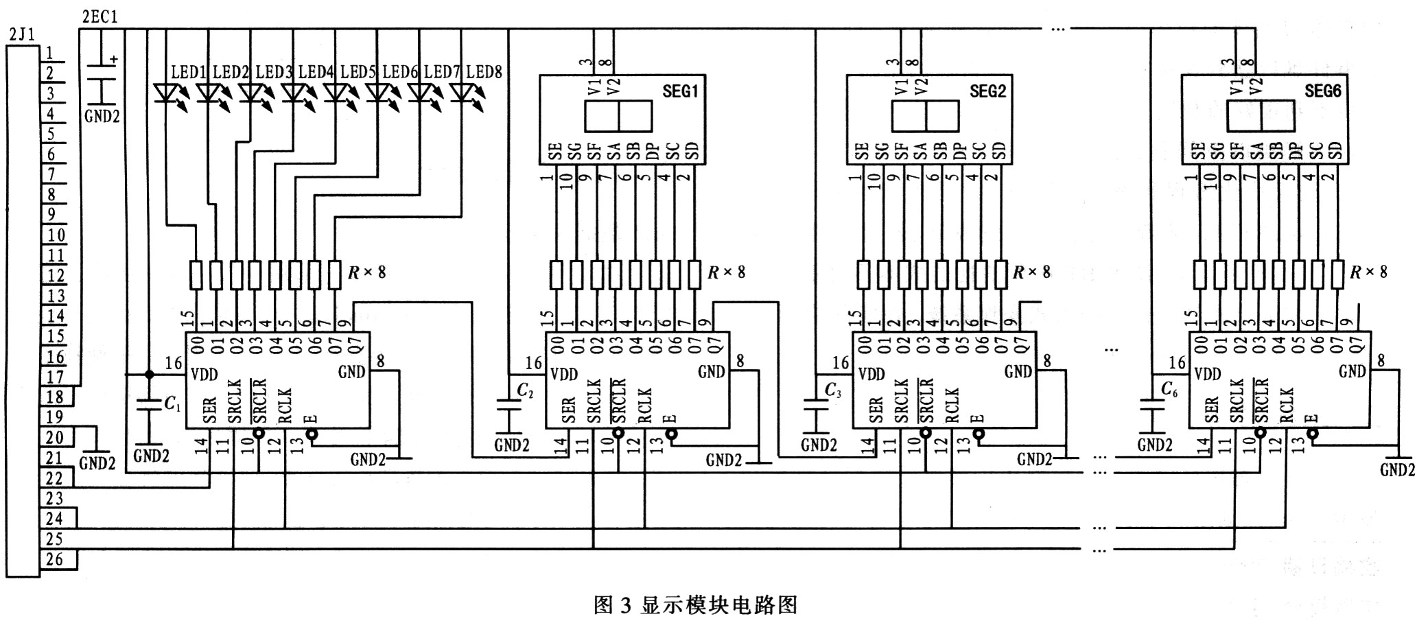
3.3 Display and communication module display driver adopts SN74HC595, which is a serial input parallel output shift register. It only needs 3 I/O port lines to control 6 digital tubes and 8 LEDs, which greatly saves The resources of the microcontroller, the circuit shown in Figure 3.

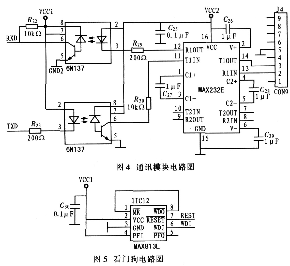
The communication module adopts MAX232 and adopts optical isolation design to improve the anti-interference ability of the instrument, as shown in Figure 4.

3.4 Buttons and External Watchdog Circuit The keyboard uses a typical 4x4 matrix membrane keypad to set meter parameters. In order to improve the anti-interference ability of the instrument and enhance the stability of the instrument, an external watchdog reset circuit is adopted. The device selected is the MAX813, and the circuit is shown in Figure 5.
4 system software design
4.1 Introduction to Small RTOS51 Small RTOS5l is an embedded real-time operating kernel designed for 5l series single-chip microcomputers. It can be directly used by Keil compiler. Its features: 1 open source code. As long as you follow the license agreement, anyone can get the source code for free, which is convenient for users' secondary development. 2 portability. The user can compress the CPU-related control commands to a minimum. Applications can be written in ANSIC, which not only simplifies programming but also facilitates program porting. 8 curability. The Small RTOS51 is designed for embedded systems and can be embedded into the product as part of the product. 4 preemptive operation. Small RT0S51 can manage 16 user tasks, each of which can be set to a different priority. Small RTOS5l always runs the highest priority task. 5 interrupt management. Adopt interrupt management. When there is a more advanced interrupt request, the task currently being executed is suspended. If a higher priority task is awakened by an interrupt, the high priority task is executed immediately after the interrupt nesting ends. The number of interrupt nesting layers can be up to 255 layers. Nested management of interrupts can be disabled if needed. 6RAM demand is small. SmallRTOS51 is designed for small RAM systems, so the demand for RAM is only a few hundred bytes, and the corresponding system services are few.
4.2 System software implementation According to the functions to be realized by the instrument, the whole system is divided into multiple parallel tasks. The preemptive operation kernel schedules the tasks according to the priority of the tasks. Here the system is divided into 8 tasks, sorted in order of their priority from high to low. It is implemented by the task establishment function OS-TaskCreate provided by the operating system.
(1) Task_AD is responsible for receiving the A/D converted data, that is, the sampling of the signal, and determining whether it is the axle weight data, and if so, saving. After receiving the A/D converted data through the interrupt service routine, a semaphore AD_Sem is sent after the completion of the reading, and the Task_AD task starts to determine whether to save the data after receiving the AD_Sem semaphore. If the task detects that an axis has completely passed through the scale, it sends a message for the corresponding axis to the data processing task.
(2) Task_Identify is responsible for identifying the axle type of the car and whether the car is completely through the weighing platform. According to national regulations, different axle types have different load-limiting loads. Therefore, when weighing dynamically, the meter should automatically identify the axle type of the vehicle, and then judge whether it is overloaded according to the limit weight of the axle-type car. The task also identifies whether the vehicle is completely passing through the weighing table by scanning the signal from the vehicle separator. The End_Sem semaphore is sent if it is recognized that the vehicle has completely passed through the weighing platform.
(3) Task_Comm_Rece is responsible for receiving commands from the host computer and sending requests from the response meter. The meter performs the corresponding operation through different commands sent from the host computer.
(4) Task_Key is responsible for the scanning and recognition of the keys.
(5) Task_Data is responsible for the processing of weighing data. When the task receives the axis information sent from the Task_AD task, it starts processing the data of the axis. The weight of the shaft is calculated by a weighing algorithm. The weight is sent to the Task_Display task as information.
(6) Task_Display is responsible for displaying weight and parameters. The task receives the information sent by the data processing, and will display the weight of the axis. If the meter detects that the car has completely passed the scale, the total weight of the car is displayed. If the Task_Key task scans to the parameter key, it switches to the parameter display state.
(7) Task_End is responsible for a series of processing work after the car has completely passed the weighing platform, including total weight accumulation, shaft group weight statistics, and shaft type statistics. After processing, the information is sent to the data communication information queue, and the data transmission task is notified to send the corresponding data to the upper computer.
(8) Task_Comm_Send is responsible for sending data to the host computer. When the task receives the communication message, it sends different data to the host computer according to different information values. For example, if the car is passing through the weighing table, the communication information value is 1. After receiving the message, Task_Comm_Send will send the weight information and the axis type information of the vehicle to the host computer. If the car passes through the weighing table in reverse, the communication information value is 0, and the Task_Comm_Send receives the information to send the vehicle's reverse information to the host computer.
5 Conclusion Using the embedded operating system as the development platform can improve efficiency, avoid complex loops and judgment structures in traditional development, and reduce the difficulty of program maintenance. Through reasonable task division, the requirements of real-time, reliability and accuracy of the system can be met.
China Area Array Sensor
Area Array Sensor,Passive Infrared Detector,Infrared Heat Detector,Infrared Area Sensor
Ningbo NaXin Perception Intelligent Technology CO., Ltd. , https://www.nicswir.com