High-speed DACs are widely used in wireless communications, wireline communications, and electronic test equipment. Today's high-speed DAC products are far from having only one core for digital-to-analog conversion, including more and more digital signal processing. This article briefly discusses the digital signal processing related content in high speed DACs.
One of the most common digital signal processing units in high speed DACs is interpolation. First we discuss the effects of interpolation and corresponding filters.
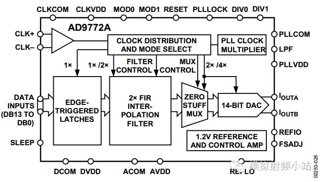
Here we take the AD9772A, an older DAC product, as an example. It can be seen in the block diagram that there is x2 interpolation and zero padding. There are two types for double interpolation: low pass interpolation and high pass interpolation. The figure below shows the principle and effect diagram of low-pass 2 times interpolation.
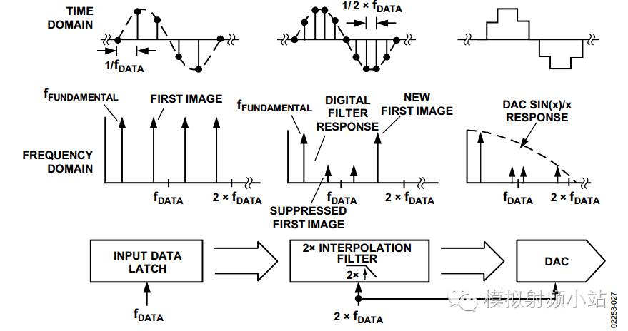
It can be seen from the above figure that the low-pass 2x interpolation is the same direction interpolation, and the image at the original fDATA-fFUND is well suppressed, but a new image is generated at 2*fDATA. But the image is far from the useful signal and is easy to handle with a filter.
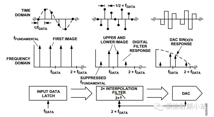
The figure above corresponds to the principle and effect diagram of Qualcomm's 2x interpolation. The Qualcomm 2x interpolation is out of phase interpolation. The fundamental signal is suppressed and the image signal is preserved. This result is well suited for use on IF emissions. This makes it possible to move the signal to an IF after passing the DAC at a low interface rate.
Next we will look at the effect of Zero Stuffing.
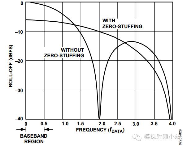
Now the signal bandwidth in communication systems is getting wider and wider, considering the SINC roll-off of the DAC itself will reduce the flatness within the signal bandwidth. At this time, the zero-padding method can be used to enhance the flatness, but this will inevitably weaken the suppression of the image.
As technology advances, the interpolation ratios supported in high-speed DACs are getting higher and higher, while adding more modulation and filtering functions. The block diagram of the AD9779A is shown below.
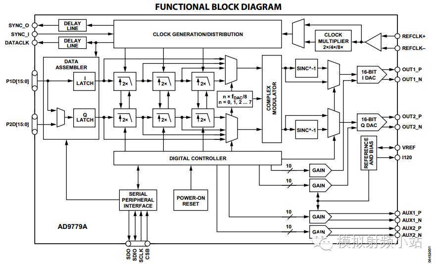
IQ signals are increasingly used in modern communications. There are two advantages to using IQ. One is to obtain a wider signal bandwidth, and the other is to have better image rejection. It can be seen from the figure that the AD9779A supports up to 8x interpolation and adds complex modulation so that the signal frequency can be moved in 1/8FDAC steps. At the same time, in order to obtain better in-band flatness, the SINC-1 filter is added to compensate for the roll-off of the DAC's own frequency response.
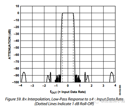
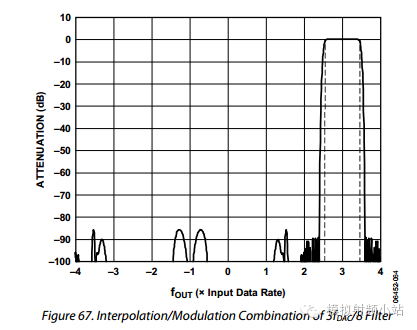
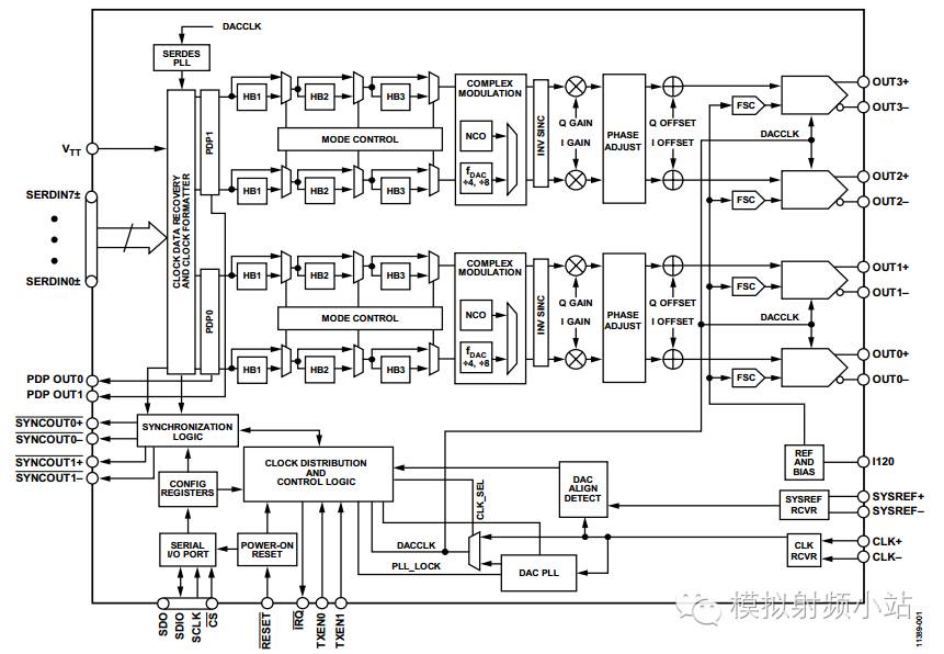
The figure above shows the frequency response diagram of the 8x interpolation low-pass filter and the interpolation and modulation. After debugging, people used more degrees of freedom for the position of the IF. However, it is still not in any position within the belt. In order to obtain greater freedom of IF position, the NCO was added later. The four-channel high-speed product AD9154 is shown below.
Litz Wire Typical applications are: high frequency inductor, transformer, frequency converter, fuel cell, the horse, communication and IT equipment, ultrasound equipment, sonar equipment, televisions, radios, induction heating, etc.In 1911, New England became the first commercial manufacturer in the United States to produce the Leeds line.Since then, New England has remained the world leader in providing high-performance Leeds line products and solutions to customers around the world.It is also transliterated as the "litz line".

Litz Wire,Copper Litz Wire,Copper Transformer Litz Wire,High Temperature Litz Wire
YANGZHOU POSITIONING TECH CO., LTD , https://www.yzpstcc.com