Detailed steps for manual soldering of patch components
With the advancement of the times and technology, more and more circuit boards now use SMD components. SMD components are more and more popular for their small size and easy maintenance. But for many people, they are "feared" by SMD components, especially for some beginners, because they think they do not have the ability to solder components, and they feel that it is not as easy to solder and grasp as traditional in-line components. These worries are completely unnecessary. Readers can use appropriate tools and master some knowledge of hand-soldering patches, and they will soon become experts in soldering patch components.
1. The benefits of using SMD componentsFirst, let's understand the benefits of SMD components. Compared with leaded components, chip components have many advantages. The first aspect: small size, light weight, easy to store and mail. For example, the commonly used chip resistor 0805 package or 0603 package is much smaller than the in-line resistor we used before. Dozens of in-line resistors can fill a bag, but if it is replaced with chip resistors, it is enough to hold thousands or even tens of thousands. Of course, this is regardless of the maximum current it can withstand. The second aspect: SMD components are easier to solder and disassemble than straight-in components. SMD components do not need vias and use less tin. The most troublesome and most troublesome part of in-line components is disassembly. Friends who have done it have this experience. Even if there are only two pins on a PCB board with two or more layers, it is not easy and easy to remove it. Damage the circuit board, not to mention multi-pin ones. It is much easier to disassemble the SMD components. Not only is it easy to disassemble the two pins, even if the components with one or two hundred pins are disassembled several times, the circuit board will not be damaged. The third aspect: SMD components also have a very important advantage, that is, to improve the stability and reliability of the circuit, which is to improve the success rate of production.
This is because the SMD components are small in size and do not require vias, thereby reducing stray electric fields and stray magnetic fields, which are particularly important in high-frequency analog circuits and high-speed digital circuits. The review said that the author can be "responsible", as long as you adapt to and accept the SMD components, unless you have to, you may never want to use in-line components anymore.
2. Common tools needed for soldering patch componentsAfter understanding the benefits of SMD components, let us understand some of the basic tools required for soldering common SMD components (see Figure 1).
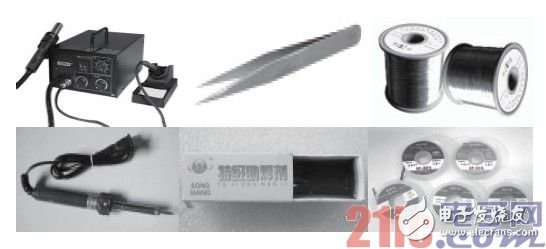
Figure 1 Common tools used for manual soldering of patch components
1. Electric soldering iron
Hand soldering components, this is definitely indispensable. The tip of the soldering iron is recommended here, because it can accurately and conveniently solder a certain pin or a few pins when soldering a chip with dense pins.
2. Solder wire
Good solder wire is also very important for SMD soldering. If possible, use thin solder wires as much as possible when soldering SMD components, so that it is easy to control the amount of tin supply, so that there is no waste of solder and the trouble of sucking tin.
3. Tweezers
The main function of tweezers is to facilitate the clamping and placement of chip components. For example, when soldering chip resistors, tweezers can be used to clamp the resistor and place it on the circuit board for welding. Tweezers need to be pointed and flat to facilitate clamping of the components. In addition, for some chips that need to prevent static electricity, anti-static tweezers are needed.
4. Suction tape
When soldering SMD components, it is easy to have too much tin.
Especially when soldering densely multi-pin SMD chips, it is easy to cause two or even multiple pins adjacent to the chip to be short-circuited by the solder. At this time, the traditional solder suction device does not work, this time you need to use a braided solder suction tape.
Suction tape can be bought at a place where soldering equipment is sold. If you don't have one, you can use copper wire in the wire to replace it, as will be described later.
5. Rosin
Rosin is the most commonly used flux during soldering, because it can precipitate oxides in the solder, protect the solder from oxidation, and increase the fluidity of the solder. When soldering in-line components, if the components are rusty, they should be scratched first, then put them on the rosin and iron them with a soldering iron, and then tin them. When soldering SMD components, rosin can also be used as a tin suction tape with copper wire in addition to the soldering function.
6. Solder paste
Solder paste can be used when soldering iron parts that are difficult to tin. It can remove oxides on the metal surface and is corrosive.
When soldering SMD components, sometimes it can be used to "eat" the solder to make the solder bright and firm.
7. Hot air gun
The hot air gun is a tool that uses the hot air blown from the gun core to weld and disassemble the components. The process requirements used are relatively high.
The heat gun can be used from removing or installing small components to large integrated circuits. In different occasions, there are special requirements for the temperature and air volume of the hot air gun. If the temperature is too low, the component will be soldered, and the temperature will be too high to damage the component and the circuit board. Excessive air volume will blow away small components. For ordinary patch welding, the hot air gun is not necessary, so I won’t describe it in detail here.
8. Magnifying glass
For some SMD chips with very small and dense pins, after soldering, you need to check whether the pins are soldered properly and whether there is a short circuit. At this time, it is very laborious to use the human eye, so you can use a magnifying glass to easily and reliably view each The soldering condition of the pins.
9. Alcohol
When using rosin as a flux, it is easy to leave excess rosin on the circuit board. For the sake of beauty, you can use an alcohol cotton ball to wipe clean the residual rosin on the circuit board. 10. In addition to the above-mentioned common tools for soldering, there are some such as sponge, washing water, Stiff brush, glue, etc. I won’t go into details here. If you have the conditions, you can learn about it and use it.
(From left to right, the first row is: hot air gun, tweezers, solder wire. The second row is: electric soldering iron, rosin, tin suction tape)
Third, the manual soldering steps of patch componentsAfter understanding the patch soldering tools, the soldering steps will now be described in detail.
1. Clean and fix PCB (printed circuit board)
Before soldering, check the PCB to be soldered to ensure that it is clean (see Figure 2). The oily fingerprints and oxides on the surface should be removed so as not to affect the tin. When soldering the PCB by hand, if conditions permit, it can be fixed with a soldering station to facilitate soldering. Generally, it is good to fix it by hand. It is worth noting to avoid finger contact with the pad on the PCB to affect the soldering.
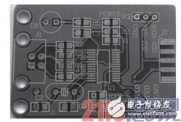
Figure 2 A clean PCB
2. Fixed SMD components
The fixation of SMD components is very important. According to the number of pins of the patch component, the fixing method can be roughly divided into two types-single-leg fixing method and multi-leg fixing method. For chip components with a small number of pins (generally 2-5), such as resistors, capacitors, diodes, triodes, etc., a single-pin fixing method is generally used. That is, tin on one of the pads on the board first (see Figure 3).
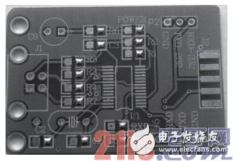
Figure 3 For components with few pins, tin on one pin first
Then hold the component with the tweezers in your left hand and place it in the mounting position and lightly hold it against the circuit board. Use the soldering iron in your right hand to close the tinned pad and melt the solder to solder the pin (see Figure 4). After soldering a pad, the component will not move, and the tweezers can be released at this time. For SMD chips with many pins and distributed on multiple sides, it is difficult to fix the chip with a single pin. In this case, multiple pins are required for fixing. Generally, the method of fixing the pins can be used (see Figure 5). That is, after a pin is welded and fixed, the pin opposite to the pin is welded and fixed, so that the whole chip is fixed well. It should be noted that for chips with many and dense pins, accurate pin alignment to the pads is particularly important, and should be carefully checked, because the quality of soldering is determined by this premise.
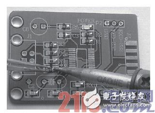
Figure 4 Fix soldering of components with few pins
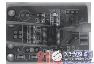
Figure 5 Fixed soldering of pins or multiple pins for components with more pins
It is worth emphasizing that the pin of the chip must be judged correctly.
For example, sometimes we fix the chip carefully and even finish the soldering. During the inspection, we find that the pin corresponds to the error-the pin that is not the first pin is used as the first pin to solder! I regret it! So these The meticulous preliminary work must not be careless.
3. Solder the remaining pins
After the components are fixed, the remaining pins should be soldered. For components with few pins, you can hold the soldering tin in your left hand and the soldering iron in your right hand, and then spot solder them in sequence. For chips with many and dense pins, in addition to spot welding, drag soldering can be used, that is, put enough tin on one pin and then use a soldering iron to melt the solder onto the remaining pins on that side (see Figure 6) , The molten solder can flow, so sometimes the board can be tilted appropriately to get rid of the excess solder. It is worth noting that whether spot welding or drag welding, it is easy to cause adjacent pins to be short-circuited by tin (see Figure 7). Don't worry about this, because it can be obtained. What needs to be concerned is that all the pins are well connected to the pads, and there is no virtual soldering.
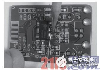
Figure 6 Drag soldering of SMD chips with more pins
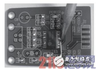
Figure 7 Don't worry about pin shorts caused by soldering
4. Remove excess solder
In step 3, we mentioned the pin short-circuit phenomenon caused by soldering. Now let's talk about how to deal with this excess solder. Generally speaking, you can use the above-mentioned suction tape to suck off the excess solder. The method of using the soldering tape is very simple. Add a proper amount of flux (such as rosin) to the soldering tape and then close it to the pad. Place a clean soldering iron tip on the soldering tape and wait for the soldering tape to be heated to the pad. After the solder on the upper part is melted, slowly push and pull from one end of the pad to the other end, and the solder is sucked into the tape. It should be noted that after the soldering is finished, the soldering iron tip and the soldering tape should be removed from the pad at the same time. If the soldering tape is stuck to the pad at this time, do not pull the soldering tape hard, but Then add flux to the soldering tape or reheat it with a soldering iron tip and then gently pull the soldering tape to make it free from the pad and prevent the surrounding components from being burnt. If there is no special suction tape sold in the market, the thin copper wire in the wire can be used to make the suction tape (see Figure 8). The self-made method is as follows: After peeling off the outer skin of the wire, expose the thin copper wire inside, and then use a soldering iron to melt some rosin on the copper wire. The effect after removing excess solder is shown in Figure 9. In addition, if you are not satisfied with the soldering results, you can reuse the suction tape to remove the solder and solder the components again.
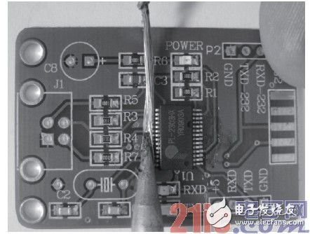
Figure 8 Use self-made suction tape to suck the excess solder on the chip pins
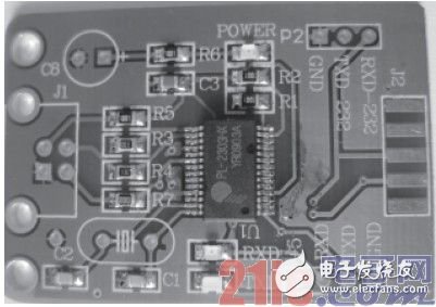
Figure 9 The effect picture after removing the excess solder on the chip pins
5. Clean the welding place
After soldering and removing the excess solder, the chip is basically soldered. However, due to the use of rosin for soldering and tin suction tape, some rosin remains around the chip pins on the board (see Figure 9). Although it does not affect the work and normal use of the chip, it is not beautiful. And it may cause inconvenience during inspection. Because it is necessary to clean up these residues. The common cleaning method can be washing plate water. Here, alcohol is used for cleaning. The cleaning tool can be a cotton swab or a toilet paper with tweezers (see Figure 10). When cleaning and erasing, it should be noted that the amount of alcohol should be appropriate, and its concentration should be higher to quickly dissolve residues such as rosin. Secondly, the erasing force should be well controlled and not too large, so as not to scratch the solder mask and damage the chip pins. The effect of cleaning is shown in Figure 11. At this time, you can use a soldering iron or a hot air gun to properly heat the alcohol scrubbing position to quickly evaporate the residual alcohol. At this point, the soldering of the chip is over.
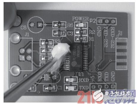
Figure 10 Use alcohol to remove residual rosin during soldering
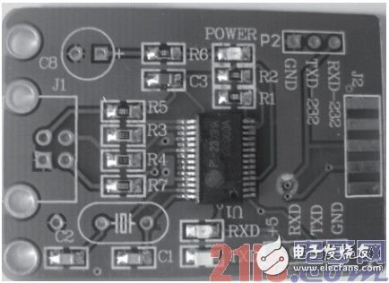
Figure 11 The effect of cleaning the welding position with alcohol
Four, summaryIn summary, soldering SMD components is generally a process of fixing-welding-cleaning. The fixing of the components is a prerequisite for good or bad soldering. You must be patient to ensure that each pin and its corresponding pad are aligned accurately. When soldering multi-pin chips, don’t worry about the pins being short-circuited by the solder. You can use a suction tape for soldering or just use a soldering iron to remove the excess solder by using the flux of the solder after melting. Of course, the mastery of these skills requires practice. Due to space limitations, only one type of multi-pin chip is soldered in this article. For many other types of multi-pin SMD chips, the pin density, mechanical strength, number, etc. are correspondingly different under different circumstances. The welding method is basically the same, but the details are slightly different. Therefore, if you want to become a master of soldering SMD components, you need to practice more to improve your proficiency. If conditions permit, you can be more proficient with old circuit boards and old chips.
Ic Logic,Logic Counters Dividers,Logic Fifos Memory,Logic Buffers Drivers Receivers Transceivers
Shenzhen Kaixuanye Technology Co., Ltd. , https://www.iconlinekxys.com