RFID (Radio Frequency IdenTIficaTIon) radio frequency identification technology has received attention in recent years, and various applications have also appeared. The promotion and technology development of many major international manufacturers have made RFID technology more mature and the cost of use has become lower and lower. RFID technology is mainly composed of inductive tags, readers/writers, and middleware. For example, Japan uses RFID to track the circulation of fresh fruits and vegetables to ensure quality. Metro Group, the world's fifth largest retailer, combines RFID and wireless networks to manage warehouse inventory and shipment information. In recent years, China has only begun to notice the technology of RFID, and related applications and research have emerged. This article will take the application of the History Museum of Southwest Petroleum University as an example, and cite two main application modes of RFID and wireless local area network, and discuss the related issues of RIFD in system development.
In addition to RFID identification technology, RFID will be combined with WLAN to explore new modes of operation for wireless and mobile computing. Two possible application architectures will be explored: mobile users combined with wireless RFID tag readers, and mobile users combined with RFID tags. When RFID tag data is used as the basis for identity and access control, it is necessary to consider possible security issues to prevent RFID tags from being used maliciously, to achieve identity forgery or unauthorized use. Therefore, this paper will also design a simple RFID data protection. Mechanism to ensure the security of authentication and authorization of RFID tags.
1 Related literature discussion1.1 Radio Frequency Identification Technology
RFID mainly emits radio waves from the reader, which can sense the RFID tag within a specific sensing range, and can read or write the tag data without physical contact. RFID tags are usually attached to items, and the reader senses the tag, quickly obtaining information about the item and further processing it, making it ideal for automated applications. Figure 1 is a schematic diagram of the operation of the RFID system. At present, RFID tags have multiple standards due to the different frequency bands and sensing technologies used. The RFID with a frequency below 13.56 MHz is usually electromagnetically induced. When the tag antenna receives the RF signal from the reader, it converts the signal into the power of the IC chip. At the same time, the command is read from the signal, and the tag is also The radio wave returns data to the reader.
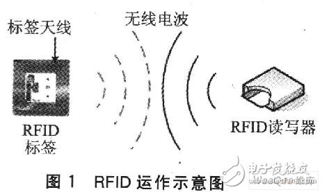
The RFID standard is mainly developed by the two standards organizations EPC and ISO. According to the ISO standard, RFID can be divided into low frequency below 135 kHz, high frequency of 13.56 MHz, ultra high frequency of 860 to 930 MHz, and microwave of 2.45 GHz and 5.8 GHz. The higher the frequency band used, the higher the sensing distance, the larger the emission radius, and the faster the reading speed, but the higher the cost. RFID can be divided into two categories: active label and passive label. This article uses RFID devices that comply with the ISO 14443A standard and supports the industry standard for MIFARE contactless and dual interface smart cards.
1.2 Wireless LAN
In recent years, WLANs conforming to the IEEE 802.11 standard have gradually become basic network access services for campus networks, enterprise networks, and ISPs. At present, IEEE 802.11 WLAN is most common with IEEE 802.11b of 11 Mbps and IEEE 802.11g of 54 Mbps. On the other hand, PDAs and notebook computers that provide the above WLAN standards are becoming more and more popular. Basically, the bandwidth provided by WLANs can meet the needs of most network applications. Due to the convenience of WLAN network cabling, it is very suitable for providing network access services in some special public places, so WLAN-based related network applications have emerged.
The IEEE 802.11 WLAN provides two modes of operation: Ad Hoc mode and Infrastructure mode. The main difference is whether an Access Point (AP) is used. At present, most WLANs adopt the In-frambling mode, that is, the mobile device achieves the purpose of communication or access to the wired network through the AP. FIG. 2 is a schematic diagram of the WLAN operation in the infrastructure mode.
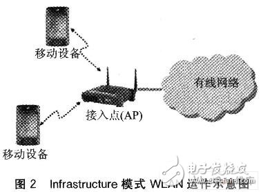
In an environment where there is no obstacle in the open air, a standard IEEE 802.11 AP signal covers a range of approximately 100 m, and indoor environment communication ranges from approximately 30 m. All mobile devices accessing the same AP communicate using the same channel provided by the AP and form a Basic Setvice Set (BSS). The AP usually connects to the wired network and can form a distributed system (DistrmuTIon Syslcln, DS) with other APs connected to the same wired network. In this way, multiple BSSs and wired networks can be combined to form an extended service set (Extended Service). Set, ESS). The ESS is to extend the service range of the WLAN. With this setting, the user can roam between the communication ranges of different WLAN base stations, but the network connection is not interrupted, which is suitable for a wide range of applications. This paper builds an application system combining RFID and WLAN based on the 802.11b WLAN in the infrastructure mode, the ESS formed by multiple APs and the wired network.
1.3 Digital Navigation System
Digital navigation means that the navigation content is output to the user through the digital device, such as sound, text, picture, film, etc., so that the user can have a general understanding of the navigation content, and can have good interaction with the system. Through these interactions, users can have more fun while navigating. At present, most of the navigation systems are in stand-alone mode, and all the navigation contents are pre-stored in the navigation device, and the navigation content is selected by the user, which is inconvenient to use. In recent years, due to advances in computer and mobile communication technologies, intelligent digital navigation technology has been proposed. This article also looks at this and explores how to apply RFID and WLAN technology to provide a better digital navigation method. At present, the new navigation system mostly uses PDA as the user's mobile navigation device, and can provide intelligent navigation function with RFID or WLAN technology. The following is a discussion of two navigation system cases.
(1) Tempies of TIbet
The Temples of Tibet is designed primarily for use by visitors to visit the Tibetan temples. The navigation device uses a PDA and all navigational content is pre-stored on the PDA. The biggest feature is that the navigation content is completely displayed in the mobile device in Flash mode. The interface is easy to operate and the introduction is quite complete. However, due to the richness of its content, the file size is about 19.4MB. For a PDA with only 64MB capacity, it accounts for nearly one-third of the capacity. Therefore, the stand-alone navigation system still has a lot of functions. .
(2) Digital Navigation System of the History Museum of Southwest Petroleum University
The user uses the PDA that has the RFID reader and the earphone to read the RFID attached to the exhibition cabinet of the exhibit, and the PDA will return the corresponding navigation text and voice content from the server by the WLAN, so that the user can be based on the user. The exhibition in front of the exhibition is guided. The system also applies RFID to the rental management of the navigation device. The service personnel only need to sense the RFID device in the navigation device and the management system to complete the operation when processing the lease and return. This navigation system has roughly presented the advantages of RFID and WLAN in the exhibition product interpretation service. In fact, there are many possible applications combining RFID and WLAN, such as ticketing, user personalization services, location services, instant messaging notifications, and the like.
RFID can play different roles. The wireless RFID tag reader developed by using a PDA with a WLAN network card can be divided into two application modes depending on the object of use of the RFID reader and the RFID tag. The first application mode is that the user holds the RFID reader, and the RFID tag is attached to the application object; the other application mode is that the user holds the RFID tag and the user moves closer to the RFID reader. In the application of the school history museum, the first mode of use is the application of the digital navigation system. Moreover, the first application mode can also be applied to the user's location service or other personalized services, and if the PDA's own computing and communication capabilities are added, various context-aware and applications requiring a large number of operations conform to this application mode. The navigation system uses the characteristics of RFID short-range non-contact sensing to allow visitors to use PDA to sense the label of the exhibit and to navigate through the WLAN to obtain exhibition information from the network. In addition, since the PDA used has Bluetooth communication capability, the Bluetooth headset will be utilized in the audio navigation function of the navigation system, and the convenience of the digital communication will be fully utilized by the wireless communication technology. A second application mode of RFID in combination with WLAN is that the user holds an RFID tag. In the ticketing system of the school history museum, the data storage capacity of the RFID tag is used to record the contents of the tickets purchased by different visitors. The ticketing system uses RFID readers to read the RFID tag content of visitors and provides a variety of ticketing applications, such as age, identity, content, and time of the event, recording different information in RFID tags to achieve identity using RFID technology. Verification and access control purposes.
Based on the above research concept, firstly, a small school history space that can display RFID and WLAN characteristics is virtualized, and then a navigation and ticketing system is planned and developed for this virtual school history hall.
2.1 Guide system
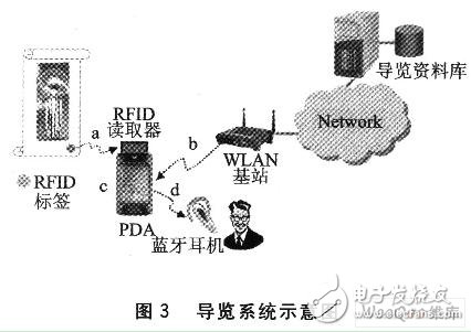
An RFID tag is placed near each exhibit object that is to provide navigation services, and a WLAN base station is established to enable the WLAN base station signal to cover all possible ranges of activity for the visitor. The WLAN base station is connected to the wired network, and the wired network has a web server as a navigation website. All the navigation content will be made into a webpage on the website, and each navigation item corresponds to a unique website. In addition, all RFID tag identifiers must be recorded in correspondence with the exhibit object. With this corresponding data, the web page redirect (redi-rect) program can provide correct navigation content based on the RFID tag identifier transmitted by the navigation PDA. Figure 3 shows a schematic diagram of the planned navigation system, the process is: a. The RFID reader reads the tag ID; b. The PDA reads the navigation content via the WLA to the web server; c. The PDA displays the navigation content; d. Transfer navigation sounds to Bluetooth headsets using Bluetooth technology.
2.2 Ticketing system
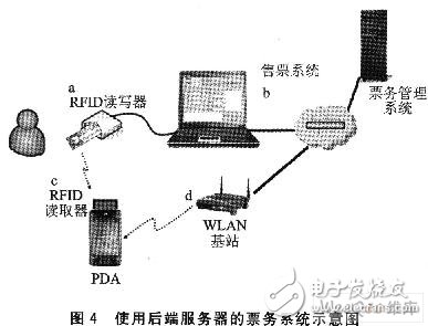
The application of RFID in the ticketing system is different from the navigation system. Users hold RFID tags instead of traditional tickets, while RFID readers are used to verify tickets. Therefore, the design of the ticketing system focuses on how to use the RFID tag as a ticket to the school history museum and how to effectively verify the legitimacy of the ticket. Tickets for the University History Museum are usually available for different fare tickets depending on the identity of the visitor, age or visits or venues. The use of RFID tags instead of traditional tickets should also provide the same functionality. In general, RFID tags have an ID identifier that is unique and cannot be copied or tampered with, and can identify legitimate RFID identifiers to achieve basic ticket verification. There are two ways to record RFID tickets: recorded in the ticketing system server database, stored in the memory of the RFID tag itself. Figure 4 shows the first ticketing system for recording the ticketing content. The basic process is: a. The visitor purchases the ticket, and the RFID reader reads the RFID tag ID; b. The ticketing system stores the ticketing contents to the ticket management system; c. Visitors hold RFID tickets to visit, and the library staff reads the RFID tag ID with an RFID reader; d. The PDA uses the WLAN to the ticket management system to read the ticket content.
2.3 RFID ticket security mechanism
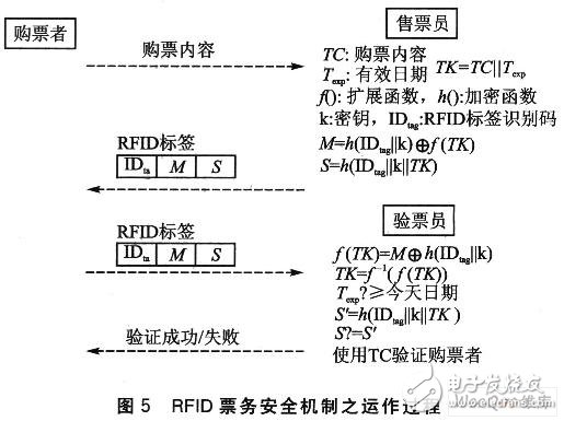
Due to the wireless communication characteristics of RFID and WLAN, possible security issues must be considered in practical applications. The function that the RFID tag identifier cannot cover at least guarantees the uniqueness of each RFID tag and prevents the use of the security attack of copying the RFID tag. Basically, there is no need to worry about the illegal copying of RFID tickets. However, the memory content of the RFID tag allows reading and writing. If the content of the RFID ticket is directly stored in the memory in plain text, the malicious attacker can easily analyze the read content, modify it, and then rewrite the RFID tag memory to achieve a security attack. the goal of. Therefore, when using the RFID tag memory to store the content of the ticket purchase, there must be a ticket security mechanism to avoid the above security threat. This paper proposes a ticket security mechanism using a one-way hash function, which utilizes the uniqueness of the RFID tag to make the ticket content data stored in each RFID different, so as to prevent malicious attackers from guessing the ticket content. Figure 5 illustrates the operation of this RFID ticketing security mechanism.
3 system implementationBased on the above ideas, build a system to verify the feasibility of the architecture. The RFID equipment required for the system was purchased from Giga-Tms. The RFID tag contains 1KB of read-only memory (EEPROM), and the RFID reader is inserted into the HP iPAQ 4700 PDA using a CF adapter card reader. The RFID device is in compliance with ISO 14443A and MIFARE industry standards. 13.56 MHz, interface transmission rate 19 200 bps, sensing distance of about 2 ~ 3 cm. The WLAN part uses a Cisco Aironet 350 AP that complies with the IEEE 802.11b standard to connect to the wired network. The navigation system on the wired network and the ticketing system server use a PC and have a built-in website server. In the software design, the C# language is used in the Pocket PC operating system to communicate with the RFID reader using the COM interface communication program, and the navigation system is developed using the Web browser control and the HTTP communication protocol. Figure 6 shows the system architecture of the system design.
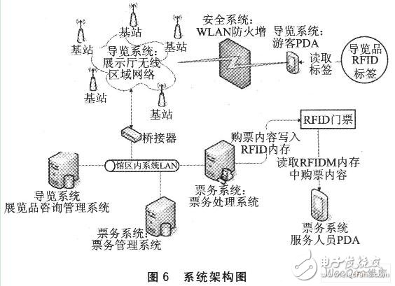
The system includes two parts: the navigation system and the ticketing system. Before the navigation system is executed, the PDA serial communication port position of the RFID reader (CF interface) must be set and the transmission rate (baud rate) of the serial communication port should be the same as the reader radio frequency (RF). When the PDA successfully establishes a connection with the RFID reader, the navigation program begins to execute and continuously monitors the data transmitted by the RFID reader. When the RFID reader senses the RFID tag, it automatically passes in the ID identifier. The navigation program uses the ID identifier as a URL parameter to launch the built-in browser, and the browser loads the related introduction page from the navigation server. The navigation page with embedded Flash animation, text and voice will start playing, and the navigation voice will be transmitted to the Bluetooth headset via Bluetooth. Figure 7 shows the PDA navigation screen.

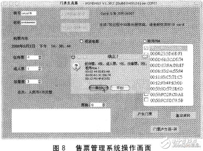
In the ticketing system, the ticket management system is developed on the PC, and the connection is made with the RFID reader using the COM communication port connected to the PC. After that, the ticket management system establishes a connection with the ticket database. After an RFID ticket is locked, the ticket fare, the remaining saleable ticket information, and the ticket sales are obtained from the ticket database. In addition, the ticket management system also undertakes a guided tour of the PDA rental business. After confirming the content of the ticket purchase, the ticket management system stores the ticket record in the ticket database, and writes the ticket content into the memory of the RFID ticket according to the RFID ticket security mechanism herein. In addition, a ticket verification program is designed on the PDA responsible for the ticket inspection. The PDA reads the RFID ticket RFID tag identifier and two 512-bit data via the CF interface RFID reader, and the security mechanism performs verification. Figure 8 shows the actual operation screen of the ticket sales management system, and Figure 9 shows the screen displayed on the PDA after the ticket verification program verifies the RFID ticket.
In view of how to use RFID and WLAN wireless communication applications, this paper proposes two possible application modes, and shows the characteristics of the school history museum navigation system and ticketing system. In the research process, the importance of RFID memory data protection was discovered, so the RFID ticket security mechanism was designed. This security mechanism can be widely used for the protection of RFID memory data. With the development of RFID-related technologies, it can be as common as WLAN and has a lower price. At that time, various applications combining RFID and WLAN will be easier.
Solar home energy storage power supply
SHENZHEN CHONDEKUAI TECHNOLOGY CO.LTD , https://www.szsiheyi.com