The rare earth fluorescent lamp for illumination has the outstanding advantages of high luminous efficiency, good color rendering, and comfortable light color, and is more and more popular. The phosphors used are yttrium-activated yttrium oxide (red powder), yttrium and lanthanum activated magnesium polyaluminate (green powder) and yttrium activated polyaluminum lanthanum magnesium (blue powder). The ratio of the three powders directly affects the luminous flux, light decay, color temperature and color rendering of fluorescent lamps, especially for the color tolerance and luminous flux of fluorescent lamps.
Due to the different densities of the three powders (red 5.18, green powder 4.22, blue powder 3.85), it is easy to cause color temperature difference in production. Once it appears, adjust the color tolerance to adjust the color temperature difference to ensure the lamp. The color of the light, and the adjustment of the color tolerance will cause other parameters of the lamp to change, especially the light output of the lamp is more complicated. Therefore, the ratio of the three powders in the production and the control coating process are very important.
2 Experimental situation and results
In general, the red powder and green powder have less light decay, and the blue powder has a greater light decay. From this, it can be estimated that the difference in the amount of excellent coordinate drift is shown in Fig. 1. The chromaticity diagram shows that the three chromaticity coordinate points of the three powders form a triangle. All color temperature points that the rare earth tribasic toner can be adjusted to.
The experiment is to adjust the color tolerance according to the position of the monochromatic powder and reduce the color temperature difference under the premise of ensuring the luminous flux is up to standard. Several experiments have been carried out using the international leading level of three primary color powder. The experimental results are shown in Table 1 (38W3 500k rare earth phosphor) .
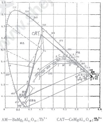
Figure 1 chromaticity diagram
Table 1 Comparison of experimental results
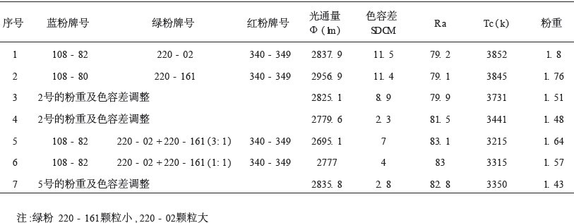
It can be seen from the experiment that although the No. 1 and No. 2 optical fluxes are high, the color tolerance is large, and the international standard value (SDCMF 5) has a small color tolerance, but the luminous flux is low. The color tolerance is large, the luminous flux is high, the color tolerance is small, and the luminous flux is low. The key is to see the area where the color point is in the color coordinate. For example, the luminous flux of No. 4 in Table 1 is greater than the luminous flux of No. 5, and the color tolerance of No. 4 is less than the color tolerance of No. 5; the luminous flux of No. 6 is less than No. 7 The luminous flux, while the color tolerance of No. 6 is greater than the color tolerance of No. 7. It can be seen from the color measurement results that the color coordinate points of the samples are different in the positional area. If the A-zone in Figure 2 has a high luminous flux, the color tolerance should be controlled in this zone, and the color tolerance should be minimized in this region, thereby achieving the purpose of reducing the color temperature difference and maintaining high luminous flux.
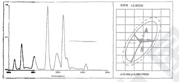
Figure 2 Light color measurement results
3 Control and adjustment
In general, red powder can increase the color rendering index (Ra), and its density is the most easy to precipitate; green powder can increase the luminous flux, and the color coordinates are generally above the center position, which is one of the reasons for controlling the color coordinate point in the A area; Blue powder can increase the color temperature Tc, but the amount of addition is small, because its light decay is large, so it can be seen that it is not optimal to control the color coordinates at the center position.
In theory, the color coordinate point should be controlled at the center position (ie, the position where the color tolerance is zero). However, in this production process, the color tolerance of the lamp is drifted outside the color circle due to process problems during the production process. For example, Experiment No. 1 and No. 2, the reason is that the characteristics of the above-mentioned single-color powder are different, the red powder has a high density and is easy to precipitate. When the powder is applied, the glass tube is placed vertically, and when the phosphor flows down from the upper end, the density of the single color powder The particle size and shape are different. The speed and stroke of the flow are different. In the case of small difference in particle size and shape, the flow rate of the red powder with the highest density is the fastest, and the flow rate of the blue powder with the lowest density is the slowest, and the first is dry. The proportion of red powder on the lamp tube is reduced, the proportion of green and blue powder is increased, the proportion is out of balance, the color temperature is changed, and the color coordinates are drifted upwards to the outside, resulting in a large chromatic aberration.
Through a large number of experiments, before the actual production, the ratio of the three base toners makes the color coordinate point control the B area in Figure 2 better, and minimizes the color tolerance, that is, also increases the proportion of red powder to compensate for the production process. The red powder is lost, so that the produced lamp eventually drifts into the A region where the luminous flux is higher.
In actual production, the color point coordinates of the sample test are in zone B, which must be adjusted by the ratio of the three base toners. As in the above experiment, it was adjusted from No. 2 to No. 4, and it was adjusted from No. 5 to No. 7 (38 W / 3500 k lamp).
1) Set the target coordinate to (x, y) in the target area B, and adjust it to the target color point (x, y) by the 2nd color point (x2, y2)
(1) Calculate Δx = x - x2 , Δy = y - y2.
(2) The ratio of the color coordinate drift of Nichia Company is calculated to increase the proportion of monochromatic powder (take 2 500 k as an example).
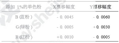
Table 2 The color coordinate drift amplitude increases the proportion of monochrome powder
The coordinates of the movement after adding a certain proportion of the monochromatic powder are the correction values ​​x', y', that is, the corrected x'= - 0. 0050, y'=- 0. 0070
(3) From the corrected coordinates x', y', the coordinates of the final movement are x1 = x2 + x', y1 = y2 + y'.
2) The color coordinate formula g11 â–³x'2 + 2g12 â–³x'â–³y'+ g22 â–³y'2= (SDCM) 2
Where △x'= x0 - x1 , Δy'= y0 - y1 , x0 , y0 are the standard color coordinates, (see Table 3).
Table 3 rated color characteristic values
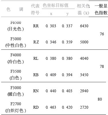
G11, g12, and g22 represent the coefficients of the standard color determined by each target (see Table 4).
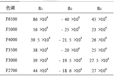
Table 4 Hue and standard color coefficient
3) The calculated SDCM can be added within the range of 1.5 SDcm to 4 SDcm, and the ratio of the monochromatic powder calculated by 1) to 2) can be added to achieve the corresponding adjustment.
4 Conclusion
In summary, the color tolerance is not adjusted to be smaller, the higher the luminous flux, the larger the non-color tolerance (SDCM), and the larger the luminous flux, but the color tolerance is adjusted according to the production process of each manufacturer and the color coordinate drift trend. The relationship of luminous flux. It is known from the experiment that the color tolerance SDCM is generally controlled in the B region of Fig. 2 of 1.5 to 4 before being put into production.
Edit: Cedar
Multi-Pin Series Glass Sealed Connectors
Multi-Pin Series Glass Sealed Connectors,Gold Plate Metal Glass Enclosure,Gtms Multipins Enclosure Terminal,Multi-Pins Feedthrough For Sensor
Shenzhen Capitol Micro-Electronics Co.,LTD , https://www.capitolgtms.com