Explain in detail the operation method of internal electric layer segmentation in OECAD
Computer Aided Design refers to the use of computers and their graphics devices to help designers design work.
In the design, a large number of calculations, analysis and comparisons of different schemes are usually carried out by computer to determine the optimal scheme; various design information, whether digital, text or graphic, can be stored in the memory or outside of the computer. Save and quickly retrieve; designers usually start with a sketch, and the heavy work of turning a sketch into a worksheet can be done by the computer; the design results automatically generated by the computer can quickly make the graph and make the designer timely The design makes judgments and modifications; the computer can perform graphic data processing related to editing, enlargement, reduction, translation, copying, and rotation of graphics.
What we will bring to gai today is: the division of the inner layer in orCAD. Explain the content: This layer assigns a complete copper skin setting parameter, assigns different colors to different power networks, adds dividing lines, splits copper, and pays attention to some precautions.
Internal layer division in orCAD
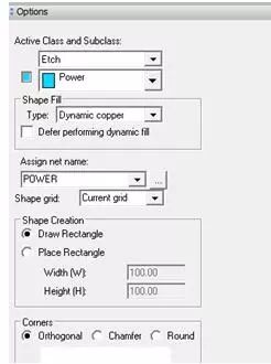
(1) This layer is given a complete copper skin
Shape/Rectangular
The Option column is set as follows
(2) Give different colors to different power networks
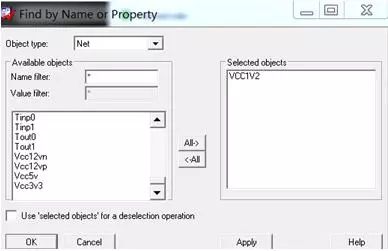
Display/Assign color
Find bar select network
Option bar select color
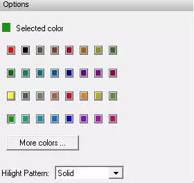
Click on the network to give color
(3) Similarly, different networks are displayed in different colors.
(4) Add a dividing line
Add/line
The Option column is set as follows
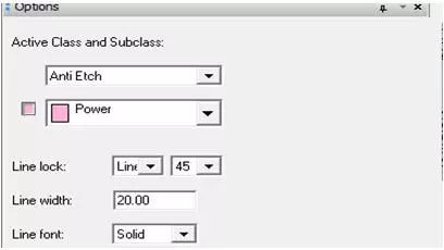
Draw a dividing line according to the distribution of the power network in the work area. Different voltages are isolated into different areas. Right click Done to complete the operation.
Note: The same power network is contained in one shape
If split at the copper boundary, the split line should be extended beyond the frame
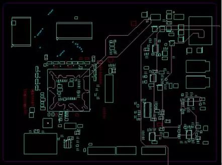
Note: 1. If space is allowed during the division, widen the isolation zone (ie the Anti-Etch layer width) to ensure the safety distance between different voltage levels.
2. Do not cover the vias connected to the power plane when adding lines in the Anti-Etch layer to avoid damaging the Flash pads.
(5) split copper
Edit/Split plane/Create

Select the type of copper to be split and the type of copper after splitting
Click Create
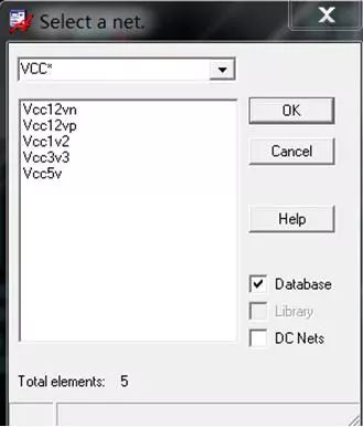
Select network, OK
Then the network is given a copper skin while highlighting the next network
Select the network name, OK
Copper all networks in turn
Results are as follows
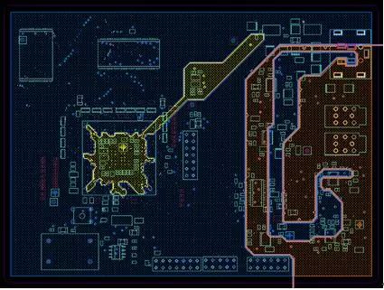
The above is the specific operation process of the inner layer division of orCAD.
Dc Gear Motor,Dc Motor 24V,220V Gear Motor,Permanent Magnet Dc Motor
NingBo BeiLun HengFeng Electromotor Manufacture Co.,Ltd. , https://www.hengfengmotor.com