In practical test applications, there are many limitations in peripheral conditions. Contact resistance, parasitic capacitance, and parasitic inductance are ubiquitous, and these factors can affect the test. This article will conduct a simulation experiment, we will learn from this experiment how the capacitance and inductance will affect it in the actual current test.
Anyone who has done the test knows that when we want to test the current, if a capacitor is added to the test end, especially after a large capacitor, the current test becomes unstable. It is possible that the test value is too large, and it may be necessary. Waiting for a longer period of time, it is possible to test a stable current value, which does not include the leakage of the capacitor itself.
Here, let's do a simulation experiment together.
Suppose we need to test the size of a resistor, we use a pressurized flow test to test. We assume that the size of this resistor R1 is about 100K. We apply a voltage across the resistor V1=5V. By testing the current through R1 (100K), we can calculate the corresponding resistance. If it is under ideal conditions, we can easily test the current of about 50uA, and then calculate the resistance of 100K.
However, in practical test applications, the presence of contact resistance, inductance, and current can affect the test.
Since the Kelvin method can be used for testing in actual tests, the influence of contact resistance can be eliminated. Therefore, only the effects of capacitance and inductance are considered here.
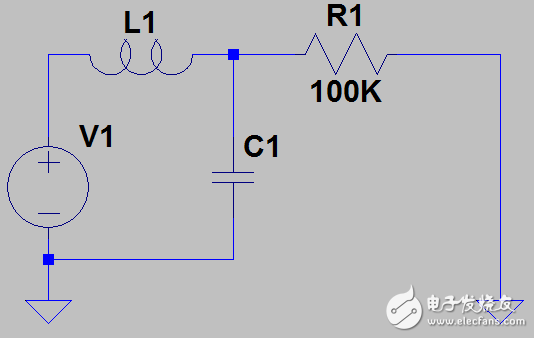
Please take a look at the following simulation circuit (using LTspice IV free simulation software, click here to download), we need to test the current through R1, and this current is actually measured by the test source V1 itself. Under actual conditions, parasitic inductance and parasitic capacitance are inevitable between the test source and the resistor to be tested. We define them as L1 and C1, respectively.

We can preset L1=10nH, C1=10nF, we assume that V1 rises from 0V to 5V and the rising TIme is 1mS.
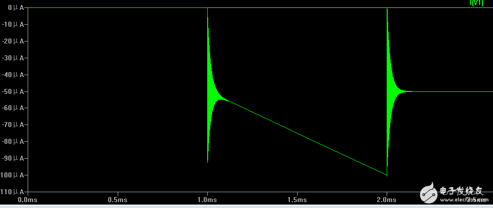
Run the simulation, we check the current through V1 (the current tested by the test source), and the simulation results are as follows:

We can find that the peak value of the current reaches about 100uA (regardless of the current direction), and the current value after stabilization should be about 50uA. Why is this 100uA current generated? This is the effect of the capacitor.
According to the calculation formula of the capacitance, we can get i=C*dV/dt. According to the known conditions, we can know that C=10nF, dV=5V, dt=1mS. By calculation, we can get i=100uA! If the capacitance C1 calculation is increased to 1uF, we can calculate i=10mA! Of course, the actual V1's rising TIme will be smaller, and the peak current will be smaller. However, due to the presence of capacitor C1, the instantaneous peak current can still be very large!
In particular, when we need to test some small currents, we often need to use a smaller current range to improve the measurement accuracy. However, due to the influence of this peak current, it may cause the test source to enter the current full scale or current clamp protection. It is impossible to test; if we increase the current range, it will affect the accuracy of current measurement!
Continue to observe the simulation map, we can also find that the current begins to oscillate at the moment when V1 rises. After V1 stabilizes (requires 1mS time), it still oscillates and gradually stabilizes after about 100uS. Since the current is oscillating, we must wait for enough time to test after the current is stable. Otherwise, the current test may be unstable.
What is the cause of this, this is the effect of inductance! In fact, this is an LRC circuit. The effect of L on the oscillation time is the greatest. If we keep the other conditions unchanged, take L1=100nH and the oscillation time reaches 2mS! If L1=1nH is taken, the oscillation time is only about 10uS.
Through the above simulation experiments, we understand the effects of capacitance and inductance in the actual test, which requires us to design a reasonable test circuit, reduce the impact of peripheral devices, and also optimize hardware design to minimize parasitic inductance and capacitance. Impact.
3500 puffs disposable vape pen are so convenient, portable, and small volume, you just need to take them
out of your pocket and take a puff, feel the cloud of smoke, and the fragrance of fruit surrounding you. It's so great.
We are China's leading manufacturer and supplier of disposable vape puff bars,3500 puff vape bar,3500 puff vape rechargeable,
3500 puffs disposable vape,disposable vape bars 3500 puffs, and e-cigarette kit, and we specialize in Disposable Vapes,
e-cigarette vape pens, e-cigarette kits, etc.
3500 puff vape bar,3500 puff vape rechargeable,3500 puffs disposable vape,3500 puffs vape pen,disposable vape bars 3500 puffs
Ningbo Autrends International Trade Co.,Ltd. , https://www.mosvape.com