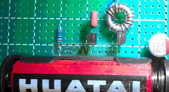
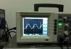
The LC oscillating circuit refers to an oscillating circuit composed of a frequency-selective network composed of an inductor L and a capacitor C for generating a high-frequency sine wave signal. A common LC sine wave oscillating circuit has a transformer feedback LC oscillating circuit and an inductor three-point LC oscillating circuit. And capacitor three-point LC oscillator circuit. The radiated power of the LC oscillating circuit is proportional to the fourth power of the oscillating frequency. To allow the LC oscillating circuit to radiate sufficiently strong electromagnetic waves outward, the oscillating frequency must be increased and the circuit must be open.
How is the lc oscillator circuit oscillating?We know that the capacitor has charge and discharge energy storage characteristics! Inductance can generate self-induced potential due to changes in current through the current!
At the moment the circuit is powered up, the capacitor will have a charging surge current! This surge current will also change the inductor current connected to the capacitor! The electric stem thus produces an induced potential! This potential is added to both ends of the capacitor so that the charging current that has ended is fluctuating! This fluctuation drives the change of the inductor current! So going back and forth, the oscillations are created!
Here are two main points! First, this oscillation will decay to disappear due to the impedance loss of the veteran and the circuit! Therefore, it is called exhaustion oscillation! To maintain the oscillations, you must have energy supplements! This is why the oscillator circuit will complement the amplifier circuit!
The second is that this oscillation has a very wide spectrum! In order to have a main frequency, it is necessary to have a fixed frequency tank! That is the frequency selection circuit!

1.1, the amplitude condition of the oscillator
The oscillator amplitude balance condition means that the amplifier's feedback signal must have a certain amplitude amplitude. The theoretical formula indicates that the product of the feedback coefficient F multiplied by the voltage amplification factor AV of the amplifier is greater than 1, that is, AvF ≥ 1, and wherein the feedback coefficient F is a number smaller than 1, thereby obtaining that the value of Av should be Greater than 1. Correctly deducing whether the amplifier is operating normally is the key to determining whether the oscillator is oscillating. When the amplifier is normally amplified, the external bias conditions of the transistor must satisfy the forward bias of the emitter junction and the reverse bias of the collector junction. Moreover, it should be noted when judging: When studying the amplification state, it is to analyze the DC state of the oscillation circuit, not the AC circuit state. It should be remembered that the inductive coil is equivalent to a short circuit in the DC state, and the capacitor is equivalent to an open circuit.
1.2, phase balance conditions of the oscillator
The second necessary condition for the oscillator to start is that the phase balance should be satisfied, that is, the feedback signal of the amplifier should be the same as the phase of the input signal. The formula in the book indicates that the phase of the feedback signal VF should be different from the phase of the input signal VI by 2nπ ( n is an integer). Since the phase of VI and VF is the same, the feedback signal can enhance the effect of the input signal. In the specific judgment of the circuit, it is to see whether the circuit is positive feedback, and whether the circuit constitutes positive feedback, generally using the instantaneous polarity method to determine. Before judging, it must be noted that whether the phase is balanced is the AC state of the circuit, not the DC state, that is, the inductor coil cannot be regarded as a short circuit in the circuit, and both ends will have a certain voltage potential difference.
The capacitor should be discussed in two cases: when in the LC circuit, the capacitor can not be considered as a short circuit, that is, there should be a certain voltage difference between the two ends. When not in the LC circuit, the capacitor can be regarded as a short circuit state; When the internal resistance of the DC power supply is small in the AC state, it can be regarded as being in a short circuit state. At the same time, it is worth noting that when the inductor coil is connected in series and two capacitors are connected in series in the circuit, when using the instantaneous polarity method, it should be considered in two cases: when the grounding point is in two series inductance or two series capacitors. At one end, the polarities of the other ends are the same, as shown by A and B in Figure 1; when the grounding point is connected to the middle of two series inductors or two series capacitors, the polarities of the two ends are opposite.

After the oscillator circuit is designed, the next step is to debug the circuit. In this process, there are often many problems. The author summarizes two common problems as follows:
2.1, the oscillator does not vibrate
After the circuit is completed, check that there is no error in the connection, and the static working point works normally, but the oscillator does not vibrate. This is mainly due to the fact that the phase balance condition and the amplitude condition are not satisfied.
1 Check whether the phase balance condition is satisfied: For the LC oscillation circuit described in this paper, it is mainly to check whether the position of the inductor and capacitor is properly arranged;
2 Check whether the amplitude condition is satisfied: If the static operating point selection is relatively low, the amplification factor of the transistor is relatively small, resulting in the circuit starting condition not being satisfied. In this case, the working point can be appropriately increased; if the feedback coefficient is too small, The size of the component parameters in the feedback circuit can be appropriately adjusted. However, if the feedback coupling is used to deal with the contradiction caused by insufficient other factors, then this is not ideal and is not suitable because if the feedback amount is too large, It may cause the waveform to be bad or even cause the circuit to not start.
2.2, the waveform of the oscillator is not ideal
When the waveform of the oscillator loop output is not ideal, or is far away from the sinusoidal waveform, the feedback amount can be appropriately adjusted to weaken the coupling. On the other hand, the quality factor of the loop is improved according to the situation. At this time, it should be noted that the static is static. The choice of operating point should be reasonable. After the oscillator is working normally, the transistor should not work in the saturation region.
In short, to achieve an ideal LC oscillator requires both mature theoretical guidance and the ability to apply the theory to the real world. Only by combining the two can achieve a multiplier effect and get a perfect sinusoidal waveform.
Customized Electronic Cigarette
Customized Electronic Cigarette,New Type Of Electronic Cigarette,Electronic Cigarette Customized,Personalized Vape Pen
Lensen Electronics Co., Ltd , https://www.lensenvape.com