Overview
FreeMASTER is provided by NXP free of charge to users, a tool to visualize data in MCU programs on a PC.
Using the FreeMASTER tool, there is no need to quote the source code related to FreeMASTER in the target project, just create the variables that need to be displayed in real time as global variables, that is, allocate a fixed address in the memory of the MCU. After that, FreeMASTER will read the value in the memory through the SWD communication interface and display it on the PC interface in real time.
Accessing memory through the SWD interface is one of the basic ways to debug Arm programs, and it works in the same way as the commonly used debuggers that support online debugging.
Hardware platform
This article uses the LPC54114-Lite development board officially launched by NXP in the Chinese market as the target device. The development board is shown in Figure 1.
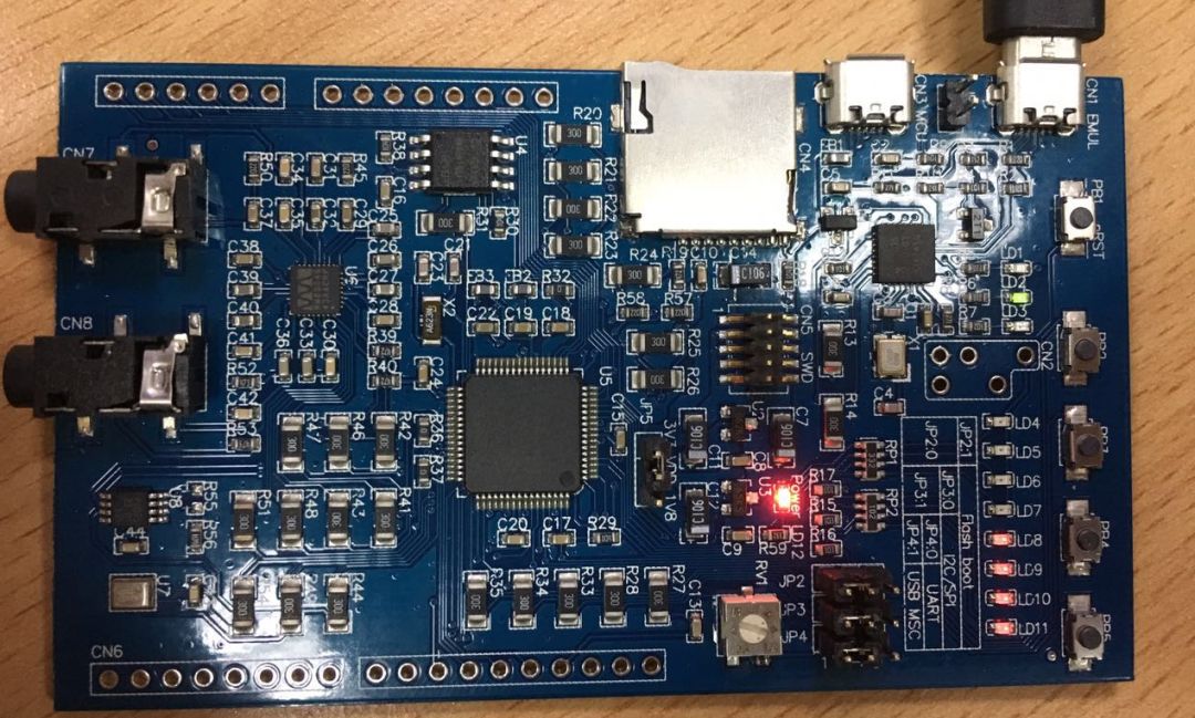
Figure 1 LPC54114-Lite development board
The LPC54114-Lite development board takes the LPC54114 microcontroller as the main control core, and the open source CMSIS-DAP debugger is integrated on the board. With only a USB data cable, it can realize the functions of power supply, debugging, and serial communication. It is suitable for portable use. And show.
FreeMASTER supports a variety of communication protocols to connect to the MCU, as shown in Figure 2, which includes the commonly used JLink and CMSIS-DSP. Surprisingly, FreeMASTER even supports the OSBDM communication protocol, which means that some Kinetis development boards based on the JM60 onboard debugger can also be used. The newer Kinetis development boards use the onboard debugger based on the K20 master. , Can be freely transformed into CMSIS-DAP, JLink or OpenSDA (using OSBDM communication protocol).
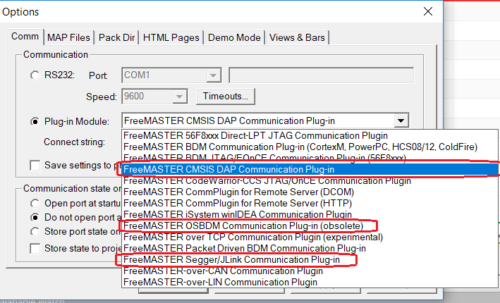
Figure 2 FreeMASTER supports multiple communication protocols with MCU
The LPC54114-Lite development board is equipped with a debugger based on LPC11u35 and built-in CMSIS-DAP firmware. This article will use CMSIS-DAP as an example to introduce the usage of FreeMASTER. Using other communication protocols is similar to CMSIS-DAP.
Create MCU sample project
When using the debug interface as the communication interface between FreeMASTER and MCU, there is an extremely obvious advantage, that is, there is no need to write any FreeMASTER code in the user program, which is so-called "non-intrusive". The user program only needs to arrange the data that needs FreeMASTER to perform graphics into global variables, so that the compilation process can allocate fixed-address memory for these data. Eventually, FreeMASTER will directly access the memory of the MCU through the debug interface to obtain displayable data.
The following uses the lpc_adc_burst project provided by NXP’s MCUXpresso SDK as the basis of the sample program to simplify and modify this project to allow ADC0 hardware to continuously sample channel 0 (temperature sensor) and channel 3 (onboard potentiometer). The sampling result is saved in the global variable array gAdcSensingValue[], and displayed on the virtual oscilloscope interface through FreeMASTER.
The key code in the main.c file is as follows:
#include "fsl_common.h" #include "board.h" #include "clock_config.h" #include "pin_mux.h" #include "fsl_clock.h" #include "fsl_power.h" #include "fsl_adc.h" / ************************************************** ***************************** * Variables ******************* ************************************************** *********/ volatile uint32_t gAdcSensingValue[2]; /******************************** *********************************************** * Prototypes * ************************************************** ***************************/ static void ADC_Configuration(void); /************** ************************************************** *************** * Code ********************************* *********************************************/ /*! * @brief Main function */ int main(void) {uint8_t ch; BOARD_InitBootClocks(); BOARD_InitBootPins(); BOARD_InitDebugConsole(); printf("HelloWorld."); ADC_Configuration(); ADC_DoSoftwareTriggerConvSeqA(ADC0 the conversion); /* software start . */ whi le (1) {ch = getchar(); putchar(ch);}} void ADC_Configuration(void) {adc_config_t adcConvConfigStruct; adc_conv_seq_config_t adcSeqConfigStruct; /* Enable power. */ POWER_DisablePD(kPDRUNCFG_PD_ADC0); /* Power on the ADC converter. */ POWER_DisablePD(kPDRUNCFG_PD_VD7_ENA); /* Power on the analog power supply. */ POWER_DisablePD(kPDRUNCFG_PD_VREFP_SW); /* Power on the reference voltage source. */ POWER_DisablePD(kPDRUNCFG_PD_TEMPS); /* Power on the temperature sensor. */ / * Enable clock. */ CLOCK_EnableClock(kCLOCK_Adc0); if (!ADC_DoSelfCalibration(ADC0)) {printf("ADC_DoSelfCalibration() failed."); while (1);} /* Configure the converter. */ adcConvConfigStruct.clockMode = kADC_ClockAsynchronousMode ; adcConvConfigStruct.clockDividerNumber = 5; adcConvConfigStruct.resolution = kADC_Resolution12bit; adcConvConfigStruct.enableBypassCalibration = false; adcConvConfigStruct.sampleTimeNumber = 7u; ADC_Init(ADC0, &adcConvConfig channelStruct); /* enable the temperature connected to 0. */ ADC_EnableTemperatureSensor(ADC0, true); /* Configure the sequence. */ adcSeqConfigStruct.channelMask = (1u
Compile and generate the "lpc_adc_burst.out" file, as shown in Figure 3. Then download and run.
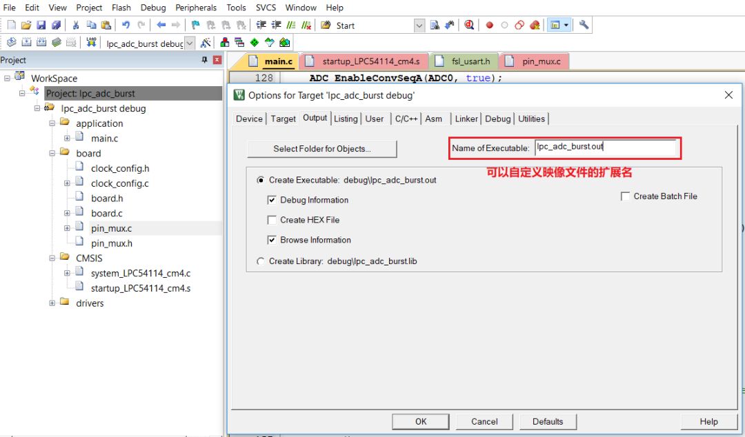
Figure 3 Setting the format of the generated image file in Keil
Note that if you download the program in debugging mode, remember to make sure to exit the debugging mode after downloading, and then use the reset button on the development board to reset the hardware. At this time, Keil should give up the occupation of the debugger, and hand over the debug communication bus to FreeMASTER in the next operation.
Create and configure FreeMASTER project
The product homepage of FreeMASTER software on NXP's official website is: https://:FREEMASTER.
Create a new project for FreeMASTER
After downloading and installing the software, start the FreeMASTER software, and a new project is created by default. Right-click the project name in the tree directory on the left, select "Properties", and edit the project name in the pop-up dialog box. In this example, change it to "lpc54114-lite", as shown in Figure 4.
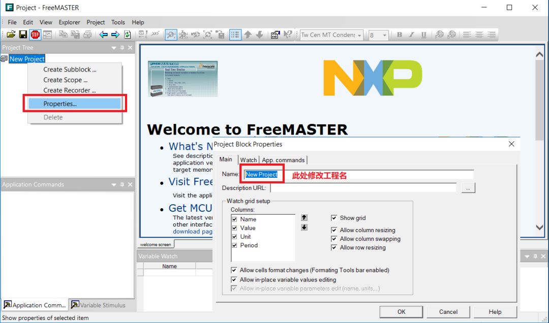
Figure 4 Create a new FreeMASTER project
At this time, you must save the project first, so that the project file has a certain file address, so that you can use the relative path when associating other files later.
Configure the communication protocol with the MCU and import the debugger file
Configure a new FreeMASTER project:
Use the CMSIS-DAP communication protocol to communicate with the main control chip LPC54114 through the CMSIS-DSP debugger onboard LPC54114-Lite.
Import the "lpc_adc_burst.out" file, FreeMASTER will automatically analyze the memory address corresponding to the variable name.
The operation is shown in Figure 5:
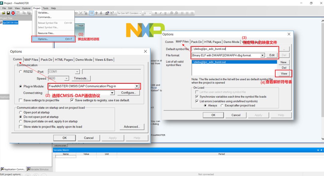
Figure 5 Configure the communication protocol with the MCU and import the debugger file
There are two main points:
It is best to use a relative path when specifying the image file of the debugger, otherwise the path of the original computer will not be recognized after the entire folder is copied to another computer.
In order to ensure that the address mapping of the variable is successfully recognized, you can click "View" to view the resolved symbol table, as shown in Figure 6.
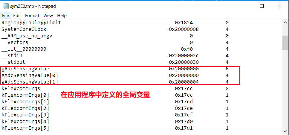
Figure 6 The symbol table parsed by FreeMASTER from the image file
Generate FreeMASTER variable table
The FreeMASTER project needs to save a list of FreeMASTER variables internally to provide operation objects for subsequent steps. The FreeMASTER variable is an encapsulation of the address on the target chip. At the same time, a regularly refreshed data cache is established in the computer's memory inside FreeMASTER, and the value of the variable in the cache is automatically updated. The variables displayed by the subsequent oscilloscope are directly read from this buffer. The operation of creating a variable table is shown in Figure 7.
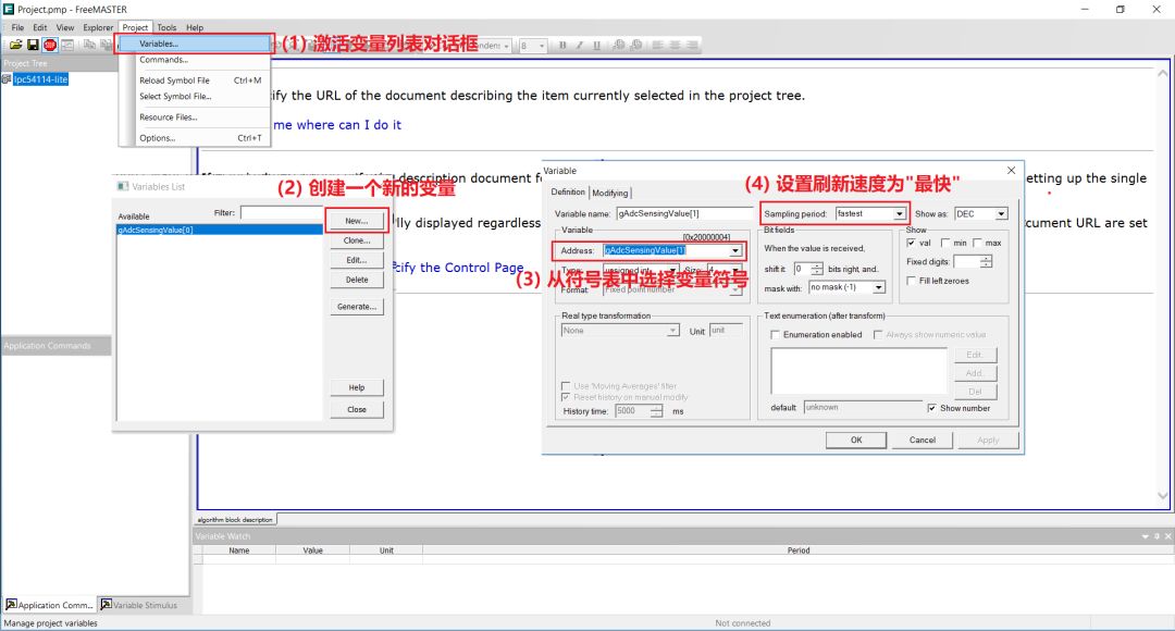
Figure 7 Generate FreeMASTER variable table
Note that only the variables created in the variable table can be recognized by the virtual oscilloscope created later.
Create a virtual oscilloscope page and set the display channel
Right-click the project name and select "New Scope..." in the pop-up menu to create a new oscilloscope page. In the Configure New Oscilloscope page, name the new oscilloscope page and specify the refresh period of the oscilloscope page. In the "Setup" tab page, specify the display channel, select the variable for the specified channel, and name the specified channel. Here, up to 8 channels are supported on one oscilloscope page, and can be displayed in groups. The operation interface is shown in Figure 8.
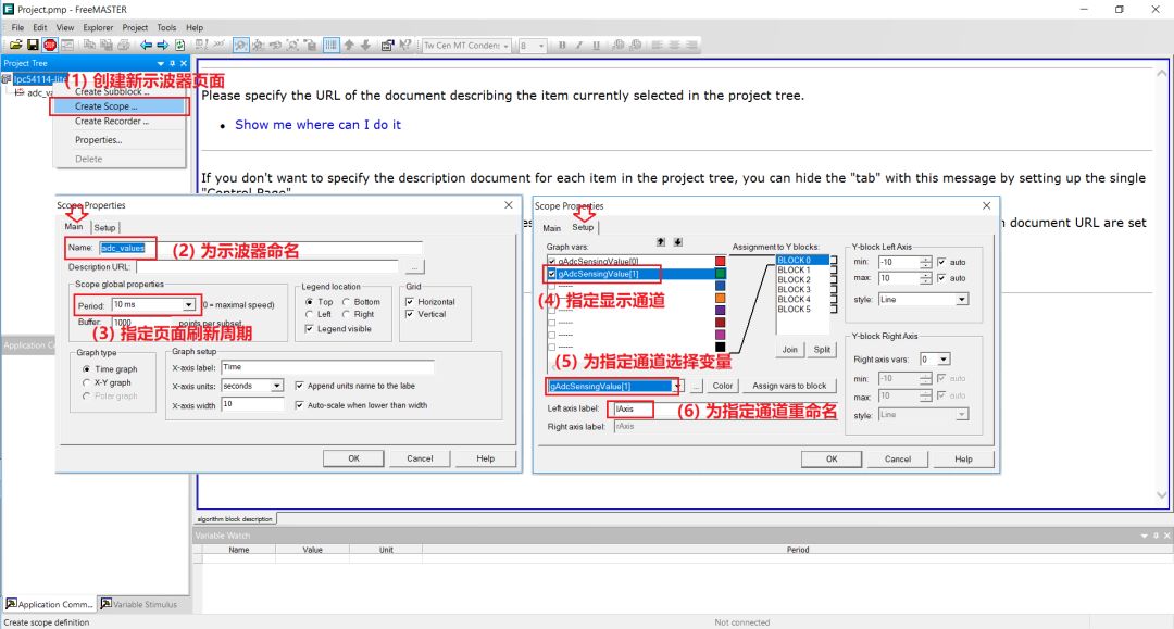
Figure 8 Create a new oscilloscope page and set the display channel
Users can create multiple oscilloscope pages under a FreeMASTER project. In addition, FreeMASTER also allows the creation of other visual data sub-modules, users can add to it by writing web pages in JavaScript and Html language.
Start the FreeMASTER project
At this time, all the configuration work has been completed. Make sure that the MCU-side program is running and that no other programs on the computer occupy the debug bus connected to the MCU, you can start FreeMASTER to start collecting and displaying data.
Click the "Start/Stop Communication(Ctrl+K)" icon in the toolbar of the FreeMASTER project window, and then you can see that there is a curve on the oscilloscope page. As shown in Figure 9.
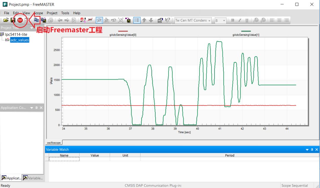
Figure 9 Start the FreeMASTER project
As you can see in the picture:
A relatively stable red curve shows the value of the variable gAdcSensingValue[0], which is the sampling value of the internal temperature sensor of the chip.
A sharply changing green curve shows the value of the variable gAdcSensingValue[1], that is, the sampled value is obtained from the on-board potentiometer. At this time, I am rotating it with a screwdriver to change the sampled value.
to sum up
Based on NXP's official LPC54114-Lite development board, this article briefly introduces the usage of the data visualization tool FreeMASTER software.
FreeMASTER can use the commonly used CMSIS-DAP debugger as the communication medium, and use the general SWD interface to communicate. There is no need to perform special communication protocol transplantation in the application. The FreeMASTER software does not need to "invade" the target program, as long as the variable to be detected is created It can be a global variable. Using FreeMASTER can quickly realize the visualization of MCU data, which is convenient for debugging.
In addition, FreeMASTER has very rich functions and powerful scalability. For example, it can automatically record data and export it to a variety of commonly used data file formats, support JavaScript and Html language programming web pages, and customize display pages. Readers of these functions will continue to explore after getting started with FreeMASTER software based on this article.
Ningbo Autrends International Trade Co.,Ltd. , https://www.vapee-cigarettes.com