Huawei's industry's first multi-probe spherical near-field SG178 test system
1. Development of antennas and near-field measurement sites
1.1 History of antenna development
Since Maxwell predicted the existence of electromagnetic waves in 1864, in 1886, Hertz used a terminal-loaded dipole as the transmitting antenna and a half-wave resonant ring as the receiving antenna. Electromagnetic waves were found in the experiment. The dipole antenna and loop antenna used by Hertz became the first laboratory antenna in human history. In 1905, Marconi set up a large square cone antenna in Bordeaux, England, and emitted a signal with a wavelength of 1000m to realize ocean-going communication. Since then, the prelude to the development of the antenna has been unveiled.
In the next century, antenna technology has achieved rapid development in three aspects: online antenna, surface antenna and array antenna:
The first stage is the development stage of the line antenna. The main representatives are dipole antenna, loop antenna and Yagi antenna. The second stage is the development stage of the planar antenna. The main representative is the reflector antenna and the lens antenna. The third stage is the array. Antenna development stage, mainly represented by phased array antenna and synthetic aperture antenna;
Antenna technology has played a major role in civil communications, satellite communications, radar, remote sensing, measurement and calibration, and new applications in these areas have effectively promoted the development of antenna technology. At the same time, the development of antenna technology poses great challenges for the measurement of high precision and high efficiency of the antenna.
1.2 Development of near-field measurement sites
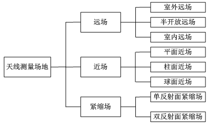
The antenna field area can be divided into an induction field area, a radiation near field area, and a radiation far field area. The antenna measurement site can be divided into three categories: far field, near field, and compact field. The specific subdivision is shown in Figure 1.

Figure 1 Antenna measurement site classification
The earliest measurement field in the field of antenna measurement is the outdoor far field. The outdoor far field is unshielded and is easily interfered by external electromagnetic signals. The reflection and scattering of the self-transmitted signal will also interfere with the test results, and the measurement accuracy is relatively low. In the early 1950s, the microwave darkroom technology appeared. The early darkroom was unshielded and the darkroom reflection performance was not high. At present, the darkroom shielding effectiveness and the quiet zone reflection performance can reach a high level. With the development of the microwave darkroom technology, the antenna measurement is transferred from the outdoor to the indoor, which solves the problem that the outdoor far field background level is high, the confidentiality is poor, and the all-weather test is not supported.
Due to the development of antenna technology, especially the deep space detection technology, large-scale reflector antennas and large-diameter array antennas have been widely used. It is difficult to meet the far-field distance required for large-diameter antenna testing in indoor far-fields. The far-field pattern of the antenna is acquired in space, thereby facilitating the generation and development of compact field and near-field measurement techniques.
The compact field converts the spherical wave into a plane wave through a reflecting surface, a lens or a holographic technique, and the far-field pattern of the antenna can be obtained at a finite distance, thereby solving the bottleneck caused by insufficient far-field distance to a certain extent. According to different application technologies, the compact field can be divided into a reflective surface type, a lens type, and a holographic type. Reflective surface compaction fields are the most widely used.
Compared with the indoor far field and the compact field, the near field has certain advantages in three-dimensional pattern test, test efficiency, and aperture field amplitude detection. The near-field measurement technology has thus achieved rapid development. The development of near-field measurement technology has gone through four stages: the first stage is the probe-free correction exploration stage (1950~1961), the second stage is the probe correction theory research stage (1961~1975), and the third stage is the experimental verification. The theoretical stage of probe correction (1965~1975), the fourth stage is the application promotion stage (1975~present). According to different sampling planes, the near-field measurement site can be divided into three types: planar near field, cylindrical near field, and spherical near field. According to the number of probes used, the near field can be divided into single probe near field and multi-probe near field. Two types.
2. Application of near-field measurement site in the field of mobile communication antenna measurement
2.1 Mobile communication antenna development trend requirements for measurement sites
The mobile communication antenna application frequency band is currently mainly concentrated below 6 GHz. The future of mobile communication antennas is moving toward multi-frequency, multi-beam, active integration and intelligence. The development of mobile communication antenna technology brings new challenges to the test function of the measurement site and the high-precision and high-efficiency measurement, as shown in Table 1. Since the near-field measurement site can meet the test requirements of mobile communication antennas in terms of test function, test accuracy and test efficiency, it is widely used in the field of mobile communication antenna measurement.
Table 1 Trends in mobile communication antennas and their requirements for measurement sites
| Mobile communication antenna development trend and its requirements for measurement sites | |||
| Antenna trend | Antenna form | Key feature | Requirements for measurement sites |
| Multi-frequency | Multi-band common antenna (700M, 800M, 900 M, 1.5G, 1.8 G, 2.1 G, 2.6 G, 3.5 G) | 1) The number of frequency bands is 2) High and low frequency common antennas, the number of arrays is large, and the antenna diameter is large. | 1) High test efficiency; 2) Support for large-diameter antenna testing; |
| Multibeam | Dual beam antenna, three beam antenna | 1) contains multiple beams; 2) beam pointing is not in the axial position | 1) can quickly and accurately find the beam pointing; 2) high test efficiency; |
| Active integration | AAS active antenna Massive MIMO antenna | 1) The RF system is fully integrated with the antenna; | 1) support air interface test; 2) support modulation signal test and OTA test; |
| Intelligent | TDD smart antenna two-dimensional adjustable antenna beamwidth adjustable antenna | 1) Contains unit beams, service beams, and broadcast beams | 1) can quickly and accurately find the beam pointing; 2) high test efficiency; |
2.2 Near field measurement site test function
The main test functions of the near field measurement site:
Antenna directivity coefficient, loss, and efficiency measurement (the near-field is calculated by integrating the three-dimensional far-field test data to obtain the antenna directivity coefficient, and then the antenna efficiency and loss information can be obtained)
Antenna gain measurement
Antenna far field amplitude pattern measurement
Antenna far field phase pattern measurement
TDD smart antenna service beam, unit beam and broadcast beam pattern test
Multi-beam antenna pattern test
Antenna phase center test
Caliber field imaging and diagnosis (cathral field imaging and array element failure diagnosis by array of near-field amplitude and phase information)
Three-dimensional pattern measurement
2.3 Near-field measurement site test accuracy and test efficiency
The near-field measurement technique obtains the far-field pattern of the antenna by measuring the amplitude and phase of the antenna and then undergoing a rigorous near-far field transform. After more than half a century of development, the theory of near-field measurement is very mature. Many international and domestic scholars have done a lot of error theory analysis and experimental verification in the near field.
In 1988, ALLEN C. NEWELL of NIST (National Institute of Standards and Technology) proposed the 18-term error theory of planar near-field on IEEE Tansactions on Antenna and Propagation. The plane was evaluated by mathematical calculation, simulation analysis and actual measurement. 18 measurement errors in the near field.
Subsequently, ALLEN C. NEWELL, Patrick Pelland, and Greg Hindman et al. further gave the error theory of cylindrical and spherical near-field.
EurAPP Working Group and ACE (Antenna Centre of Excellence) to DTU-ESA (Technical University of Denmark-European Space Agency), UPM (Technical University of Madrid), SAAB (Saab Ericsson Space), FT (France Telecom), etc. worldwide The widely-accepted near-field, compact field and far-field measurement systems have performed a large number of precision comparison verification tests. The test results show that the near-field, compact field and far-field can achieve higher test accuracy.
In the field of mobile communication, multi-probes are commonly used in near-field measurement sites. The electronic scanning method replaces the single-probe rotation mode. The antenna only needs to be tested in one installation attitude, and the test efficiency is high, especially suitable for multiple beams and intelligences that need to accurately find the beam pointing. Antennas, etc.
2.4 Near-field measurement site and indoor far-field and compact field comparison
The pair of near-field measurement sites and indoor far-field and compact fields are shown in Table 2.
Table 2 Comparison of near-field measurement sites and indoor far-field and compaction fields
| Comparison of near-field measurement sites with indoor far-field and compaction fields | |||
| Dimension | Indoor far field | Spherical near field | Tight field |
| Omnidirectional antenna | general | excellent | general |
| Directional antenna | excellent | excellent | excellent |
| Large antenna support | good | excellent | excellent |
| Band support capability | excellent | good | good |
| 3D pattern support capability | general | excellent | general |
| Amplitude pattern | excellent | excellent | excellent |
| Phase pattern | good | good | good |
| Antenna directivity coefficient, efficiency, loss | general | excellent | general |
| Test accuracy | excellent | excellent | excellent |
| Test efficiency | good | excellent | good |
| System complexity | excellent | general | general |
3. Detection method of near field measurement site
Near-field measurement site testing includes both darkroom performance testing and probe performance testing.
3.1 Near-field measurement site darkroom performance detection method
Near-field measurement site shielding performance test: Shielding performance test reference "GB-T 12190-2006 electromagnetic shielding room shielding effectiveness measurement".
Near-field measurement site static zone reflection performance detection: The static zone reflection performance detection uses free space standing wave ratio method or pattern comparison method.
3.2 Near field measurement site probe performance detection method
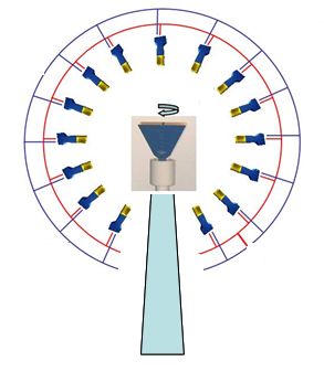
The schematic diagram of the near-field probe performance detection is shown in Figure 2. The standard horn is fixed on the two-dimensional turret. The turret rotates so that the horn can be aligned with each probe. The azimuth rotation enables the horn to rotate 360° around the probe. The turntable tooling needs to be specially designed so that when the horn is fixed on the turret, the distance from the center of the horn surface to each probe is equal.

Figure 2 Schematic diagram of near field probe performance detection
The near field requires that each probe responds consistently to the same input. The probe performance mainly includes three aspects: probe amplitude performance, phase performance and cross polarization performance. During the test, you must ensure that the test environment is the same, namely:
1) The path distance from the center of the flared surface to each probe is the same; 2) The laser should be precisely aligned so that the center of the ring, the center of the flared surface and the center of the probe are in a straight line; 3) During the test, it is guaranteed The same frequency point, the signal source output signal amplitude is consistent;
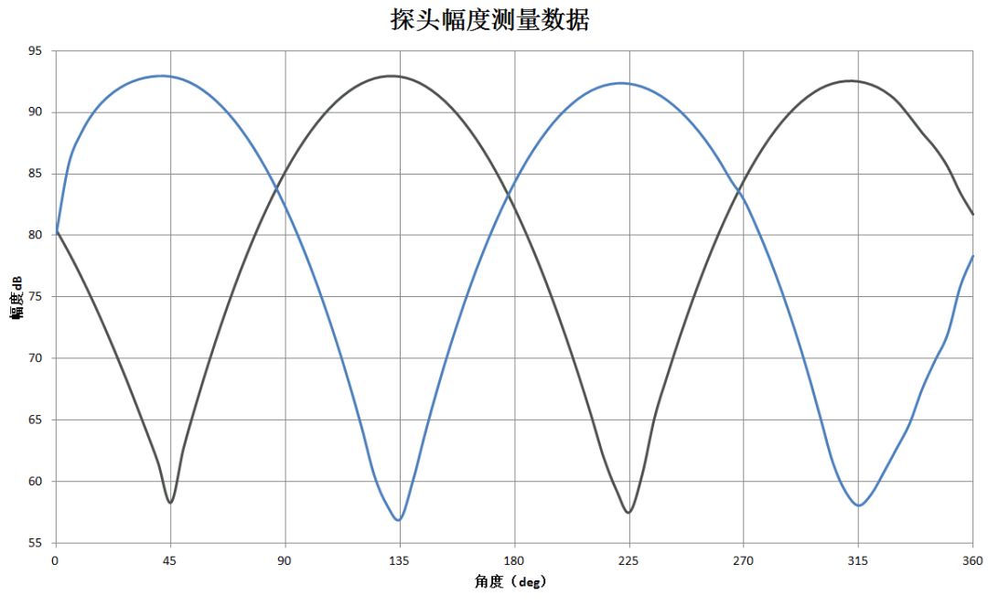
During the test, the horn rotates 360° with respect to the probe, and the amplitude and phase data received by the probe when the probe is at different polarization positions relative to the horn are measured. The curve of the receiver receiving amplitude data is shown in FIG. 3 .

Figure 3 Example of the near field probe amplitude measurement curve
The probe amplitude and phase data can be measured simultaneously. The amplitude and phase data of each probe can be processed to obtain the amplitude and phase consistency and cross-polarization performance of all probes.
4, summary
With the continuous development of antenna application fields and corresponding specifications, antenna measurement technology also faces challenges in terms of accuracy, efficiency, and test function satisfaction. Near-field measurement technology has been promoted by the above background, and after decades of development, it has become A mature mainstream testing technology has been widely used in the field of mobile communications.
Gfci Receptacle Outlet,Gfi Electrical Outlet,Gfci Protected Outlet,Outdoor Gfci Outlet
Lishui Trimone Electrical Technology Co., Ltd , https://www.3gracegfci.com