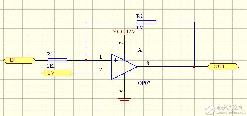
The hysteresis comparator can also be understood as a single-limit comparator with positive feedback.
Single limit comparator, if the input signal Uin has slight interference near the threshold, the output voltage will produce the corresponding jitter (fluctuation). Introducing positive feedback in the circuit can overcome this shortcoming.
Figure 1a shows a hysteresis comparator. The familiar Schmitt circuit is a hysteretic comparator. Figure 1b shows the hysteresis comparator's transmission characteristics.

It is not difficult to see that once the output state is converted, as long as the interference near the jump voltage value does not exceed the value of ΔU, the value of the output voltage will be stable. But with it comes lower resolution. Because of the hysteresis comparator, it cannot distinguish between two input voltages that differ by less than ΔU. Hysteresis comparator plus positive feedback can speed up the comparator's response, which is one of its advantages. In addition, since the hysteresis comparator plus positive feedback is much stronger than the parasitic coupling in the circuit, the hysteresis comparator can also eliminate the self-oscillation caused by the parasitic coupling of the circuit.
Hysteresis comparator
The output VO of the hysteresis comparator is not linearly related to the input VI. The critical condition for the transition of the output voltage is the threshold voltage VP (voltage at the non-inverting input) ≈VN (voltage at the inverting input)=VI (reference voltage)
VP=VN=[(R1×VREF)/(R1+R2)]+[(R2×VO)/(R1+R2)] (Formula-1)
According to different values ​​of the output voltage VO (VOH or VOL), the upper threshold voltage VT+ and the lower threshold voltage VT- can be separately found to be:
VT+={[1+(R1/R2)]×VREF}-[(R1/R2)×VOL] (Formula-2)
VT-={[1+(R1/R2)]×VREF}-[(R1/R2)×VOH] (Formula-3)
Then the threshold width is:
ΔVT=(R1/R2)×(VOH-VOL) (Formula-4)

Known operating voltage = 12V
Reference voltage VREF=1V
Input voltage VI=1~5V
R1=1000Ω=1KΩ R2=1000000Ω=1MΩ
Feedback coefficient = R1/(R1+R2)=0.000999
Comparator output voltage VOH=12V, VOL=0V
The comparator's threshold width / output voltage = feedback factor that is the feedback factor × output voltage = threshold width 0.000999 × 12 = 0.011988 ≈ 0.012V
According to (Formula-2) VT+={[1+(R1/R2)]×VREF}-[(R1/R2)×VOL]
={[1+(1000/1000000)]×1}-[(1000/1000000)×0]
=1.001-0
=1.001(V)
According to (Formula 3) VT-={[1+(R1/R2)]×VREF}-[(R1/R2)×VOH]
={[1+(1000/1000000)]×1}-[(1000/1000000)×12]
=1.001-0.012
=0.989(V)
According to (Formula-4) ΔVT=(R1/R2)×(VOH-VOL)
= (1000/1000000) × 12
= 0.012 (V)
Verification VT+-VT- =1.001-0.989=0.012(V)
The range of ΔVT can be adjusted by changing R2 to change the feedback coefficient.
For example, when R2 is changed to 10KΩ, then ΔVT=(R1/R2)×(VOH-VOL)
= (1000/10000) × 12
=1.2(V)
For example, when R2 is changed to 100KΩ, then ΔVT=(R1/R2)×(VOH-VOL)
=(1000/100000)×12
= 0.12 (V)
HuiZhou Superpower Technology Co.,Ltd. , https://www.spchargers.com