Seth Allen, project manager at Adept MobileRobots, believes that ground robot systems must often handle "boring, dirty, dangerous" work. In other words, robotic systems are often used for manual interventions that are too costly, dangerous, or inefficient. In many cases, the autonomous working ability of the robot platform is an extremely important feature that monitors and controls the movement of the robot from one position to the next through a navigation system. Managing position and motion accuracy is a key factor in achieving efficient autonomous operation. MEMS (Micro Electro Mechanical Systems) gyroscopes provide feedback detection mechanisms that are useful for optimizing navigation system performance.
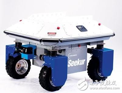
The Seekur robot system shown in Figure 1 is an autonomous system that uses advanced MEMS devices to improve navigation performance.

figure 1. Adept MobileRobots' Seekur system.
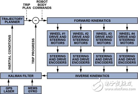
Robot navigation overviewThe movement of the robot usually begins when a position change request is made by a central processor that manages the overall task progress of the robot. The navigation system begins to execute a position change request by making a trip plan or trajectory. The itinerary plan needs to consider available paths, known obstacle locations, robot capabilities, and any related mission objectives. (For example, for a specimen delivery robot in a hospital, delivery time is critical.) The trip plan is fed into the controller, which generates the drive and direction profiles for navigation control. These profiles perform actions and processes based on the trip plan. The motion is typically monitored by a number of detection systems, each of which produces a feedback signal; the feedback controller combines and converts the signals into updated schedules and conditions. Figure 2 is a basic block diagram of a general navigation system.

figure 2. General navigation system block diagram.
The key steps in developing a navigation system begin with a thorough understanding of each function, with particular emphasis on its work objectives and constraints. Features often have some well-defined and easy-to-implement factors, but they also raise some challenging limitations that need to be addressed. In some cases, this may be a process of iterative testing, which identifies and addresses constraints while introducing new opportunities for optimization. This process can be clearly illustrated by an example.
Adept MobileRobots Seekur robot
The Adept MobileRobots Seekur2 is an autonomous robot using the Inertial Navigation System (INS), see Figure 3. The vehicle has a 4-wheel drive system with independent steering and speed control for each wheel, allowing for flexible movement of the platform in any horizontal direction. This capability is useful for robotic vehicles in emerging applications such as warehouse delivery systems, hospital specimen/refill delivery systems, and military reinforcement systems.

image 3. Adept MobileRobots Seekur navigation system.
Positive control
The robot body command, the primary error signal, represents the difference between the trip plan provided by the trajectory planner and the trip progress update information provided by the feedback detection system. These signals are fed into a reverse kinematics system that converts the robot body commands into steering and speed profiles for each wheel. These profiles use Ackerman steering relationships to perform calculations that integrate tire diameter, surface contact area, spacing, and other important geometric features. Using Ackerman steering principles and relationships, the robotic platform described above creates an electronically linked steering angle profile similar to the mechanical gear-to-rack system used in many automotive steering systems. Because these relationships are integrated remotely, there is no need to mechanically link the axles, thus helping to minimize friction and tire slip, reducing tire wear and energy loss, and achieving simple mechanical linkages that cannot be completed. .
Wheel drive and steering system
Each wheel has a drive shaft that is mechanically coupled to the drive motor through a gearbox and coupled to the optical encoder through another gearbox, the input of the range feedback system. The steering shaft couples the axle to another servo motor that is responsible for establishing the steering angle of the wheel. The steering shaft will also be coupled through a gearbox to a second optical encoder, the other input of the range feedback system.
Product introduction
The moisture absorber is used to remove and dry sundries and moisture in the air of transformer oil conservator to maintain the insulation strength of transformer oil.
The main components are hygroscopic silica gel, which can be divided into two types: single breathing and double breathing. There are white silica gel hygroscopics, color changing silica gel, and color changing silica gel can be divided into orange and blue;
Technical parameter
Applicable environment: - 30~43 ℃;
Ventilation resistance: ≤ 0.01Mpa;
Adsorption material: 75% microporous silica gel, 25% chromogenic silica gel, material particles φ 2-6mm;
Adsorption capacity: (at 20 ℃)
S/N Model Remarks S/N Model Remarks
1. 0.2Kg with distribution transformer below 80KVA 8 4Kg with main transformer below 31500KVA
2. 0.5Kg with distribution transformer below 200KVA 9 5Kg with main transformer below 50000KVA
3. 0.07Kg equipped with distribution transformer below 200KVA 10 6Kg equipped with main transformer below 100000KVA
4. 1Kg distribution transformer below 630KVA 11 7Kg main transformer below 180,000KVA
5. 1.5 Kg for distribution transformer below 2000 KVA 12 8 Kg for main transformer around 300000 KVA
6. 2Kg distribution transformer below 3150KVA 13 10Kg main transformer around 500000KVA
7. 3Kg equipped with main transformer below 10000KVA
Moisture Absorber,Silicone Moisture Remover,Transformer Moisture Absorbers,Blue Silicone Moisture Remover
Henan New Electric Power Co.,Ltd. , https://www.newelectricpower.com