Thermocouples are one of the oldest and most widely used components in temperature measurement. Applications that measure temperature in harsh environments often use thermocouples such as boilers, ovens, and automotive and petrochemical applications. Thermocouples are capable of measuring temperatures from -200 ° C to +2500 ° C, and thermocouples can react to temperature changes more quickly than other sensors. At the same time, excellent impact resistance and vibration resistance are also a cause of the widespread adoption of thermocouples.
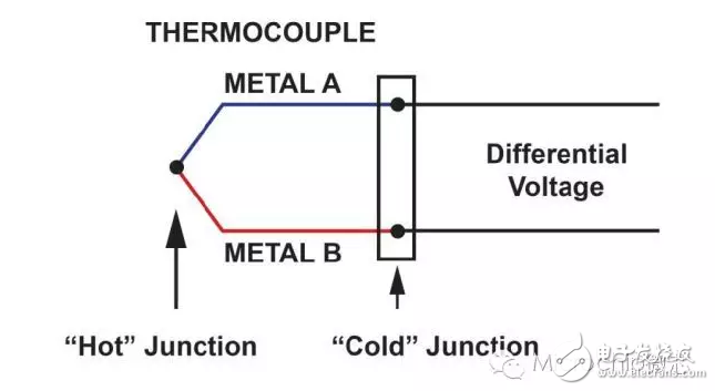
So what is a thermocouple? A thermocouple consists of two metal wires of different materials, one end of which is connected together. The end that is joined together is often called the "hot" end, and the end of the opening is called the "cold" end. As shown in Figure 1, the differential voltage between the two wires can be used to calculate the temperature at the hot end.

Figure 1: Thermocouple simplified diagram
All thermocouples must measure signal changes in the millivolt range. The most common types of thermocouples are J, K, and T, which have room temperature voltages of 52 μV/°C, 41 μV/°C, and 41 μV/°C, respectively. Since their voltage signals are small, it is difficult to extract signals from system noise. At the same time, the thermocouple output is nonlinear with temperature, so high-order equations are needed to accurately calculate the temperature. In addition, the accuracy of thermocouple measurements is closely related to the accuracy of cold junction temperature measurements, which complicates already quite complex systems. In general, thermocouple signal conditioning is the most expensive part of the thermocouple solution.
Measurement Options The differential voltage generated by the cold junction depends on the temperature difference between the hot and cold junctions. Therefore, the temperature at the cold end must be known to obtain an accurate overall temperature reading. This is called "cold end compensation (CJC)". The overall temperature accuracy of a thermocouple solution is limited by the temperature accuracy of its CJC.
Today, there are many solutions for cold junction temperature measurements such as RTDs, thermistors, and silicon-based IC temperature sensors. Thermistors are characterized by fast response and small package size, but they require linearization and accuracy is affected by a wide temperature range. At the same time, they also require excitation currents that generate self-heating and increase power consumption, which limits their use in many portable or battery-powered applications. The Resistance Temperature Detector (RTD) provides accuracy, stability, and reasonable linearity. However, package size and cost issues have limited them in many applications. The silicon-based IC temperature sensor now has a temperature accuracy of more than 0.5 °C. Silicon-based ICs are a simple device that requires very little external circuitry or thermal design knowledge. In recent years, with this simplicity and increased temperature accuracy, the use of such devices has become increasingly popular.
In general, discrete thermocouple solutions use an instrumentation amplifier (INA) to extract the thermocouple voltage, while INA rejects the common voltage at each input of the device. Because most of the noise is present on each thermocouple lead, INA can effectively filter noise.
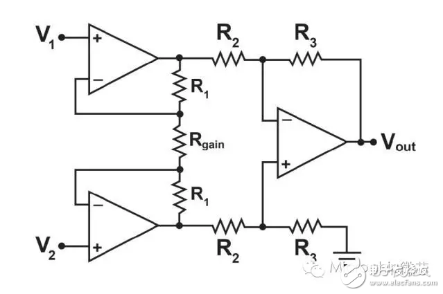
There are many instrumentation amplifiers on the market today. The traditional INA topology uses two op amps as gain stages and then feeds the gain signal to a third op amp configured as a differential amplifier, as shown in Figure 2.

Figure 2: Instrumentation Amplifier with Three Op Amps
The gain of this circuit is set with a single resistor Rgain. Although this topology can achieve a common mode rejection ratio (CMRR) above 80 dB under DC conditions, the increase in CMRR with frequency is greatly reduced. If one of the uses of this device is to suppress high frequency noise, there is a problem. Use a single resistor method that requires careful consideration. Adjust the internal resistance to a ratio instead of an absolute value. However, not knowing the absolute value of the internal resistance will make the circuit gain difficult to determine. The temperature coefficient of a single resistor relative to the external gain resistor will be different, which will result in additional gain errors over a range of temperatures.
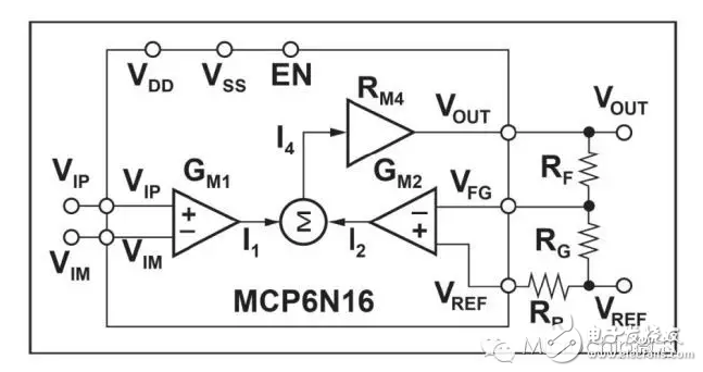
The new architecture superimposes current rather than voltage superposition, improving common mode rejection at higher frequencies. As shown in Figure 3, Microchip's MCP6N16 device is one such example. The current generated by this architecture causes the voltage across the RG to be equal to the differential voltage from VIP to VIM.

Figure 3: Functional Block Diagram of the MCP6N16 Instrumentation Amplifier
Vout = (VIP - VIM)*(1 + RF/RG)
Please note: Two external resistors are used here to set the gain, eliminating the aforementioned concerns associated with the single resistor approach.
In summary, thermocouple signal conditioning is more complicated than other temperature measurement systems. Advances in modern INA architectures and silicon-based IC temperature sensors have solved many of the historic design challenges associated with thermocouples. In addition, several major chip manufacturers have integrated many analog, mixed-signal and temperature-sensing components for CJC to further reduce overall design while improving overall system performance.
PC Cable:MINI DIN,D-SUB,SCSI.The display connecting line includes the data cable connecting the host computer and the display screen, and the power cable connecting the power supply.
The common data cable types are: HDMI cable, VGA cable and DVI cable. There is also a DP cable for notebook!
This product is suitable for computer and automatic connection cable with rated voltage of 500V and below. K type B low density polyethylene (LDPE) with oxidation resistance is used for insulation of cable ground wire core. Polyethylene has high insulation resistance, good voltage resistance, small dielectric coefficient and small influence of dielectric loss temperature and variable frequency. It can not only meet the requirements of transmission performance, but also ensure the service life of the cable. One
In order to reduce the mutual crosstalk and external interference between loops, the cable adopts shielding structure. According to different occasions, the shielding requirements of cables are as follows: the combined shielding of twisted pair, the total shielding of cable composed of twisted pair, and the total shielding after the combined shielding of twisted pair.
Shielding materials include round copper wire, copper strip and aluminum / plastic composite belt. Shielding pair and shielding pair have good insulation performance. If there is potential difference between shielding pair and shielding pair, the transmission quality of signal will not be affected.
PC Cable
ShenZhen Antenk Electronics Co,Ltd , https://www.pcbsocket.com