Mitsubishi plc and touch screen communication examples
Mitsubishi PLC English name is also known as: MitsubishiProgrammableLogicController, is the main product of Mitsubishi Electric in Dalian. It uses a class of programmable memory for its internal memory program, performing user-oriented instructions such as logic operations, sequence control, timing, counting, and arithmetic operations, and controlling various types of machinery through digital or analog input/output. Or the production process. Mitsubishi PLC has the following models commonly found in the Chinese market: FR-FX1NFR-FX1SFR-FX2NFR-FX3UFR-FX2NCFR-AFR-Q).
Mitsubishi PLC product typeFX1S Series: Mitsubishi PLC is an integrated small unit PLC. It has full scalability such as performance and communication capabilities. If you consider the installation space and cost is an ideal choice.
FX1N series:
It is a powerful popular PLC launched by Mitsubishi Electric. With extended input and output, analog control and communication, link function and other scalability. It is a widely used Mitsubishi PLC for sequential control.
FX2N series:
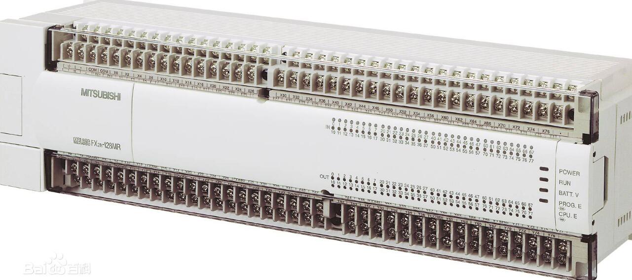
At the time, Mitsubishi PLC was the most advanced series in the FX family. Features high-speed processing and the ability to expand a wide range of special function modules to meet individual needs, providing maximum flexibility and control for factory automation applications.
FX3U series:
It is a new third-generation Mitsubishi PLC newly launched by Mitsubishi Electric Corporation, which may be called a small supreme product. The basic performance is greatly improved. The basic unit of the transistor output type has built-in 3-axis independent maximum 100kHz positioning function, and adds new positioning commands, which makes the positioning control function more powerful and more convenient to use. The FX3U series products are FX2N replacement products, and the FX2N series products are no longer available in December 2012. Everyone will choose FX3U series products in the future.
FX3G series:
It is a new third-generation Mitsubishi PLC newly launched by Mitsubishi Electric Corporation. The basic unit comes with two high-speed communication interfaces (RS422 & USB, built-in up to 32K large-capacity memory, basic command processing speed of 0.21μs in standard mode, control scale: 14~ 256 points (including CC-LINK network I/O), easy to set positioning function (up to three axes), up to 4 FX3U special adapters can be connected to the left side of the basic unit, which can realize floating point calculation, and can set two levels of passwords, each level 16 characters, enhanced password protection
FX1NCFX2NCFX3UC Mitsubishi PLC:
On the basis of maintaining the original powerful functions, the extremely large scale reduction I/O type wiring interface reduces the wiring cost and saves time.
Q series Mitsubishi PLC:
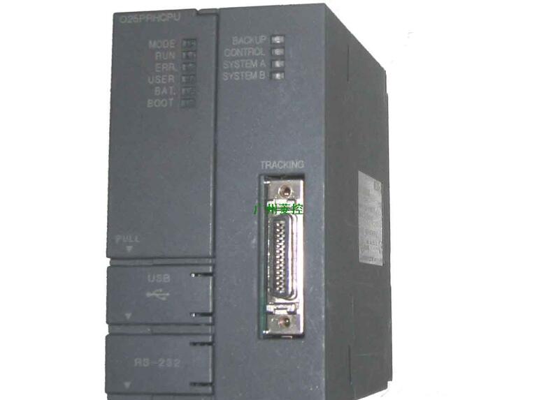
The large PLCs introduced by Mitsubishi Electric Corporation include CPUs of basic type, high-performance CPUs, process control CPUs, motion control CPUs, and redundant CPUs. Can meet a variety of complex control needs. Mitsubishi Electric's rapid development in China, in order to better meet the domestic users' requirements for high-performance and low-cost products of Mitsubishi PLC and Q series products, Mitsubishi Electric Automation has launched the economical QUATESET-type Mitsubishi PLC, which is equipped with 64 points. 5-slot Q00JCOUSET for high-density mixing unit; another 8-slot Q00JCPU-S8SET with two 16-point switching inputs and two 16-point switching outputs. Its performance is fully compatible with Q00J and fully supports GX-Developer. And so on, so it has an excellent price/performance ratio.
(1) The information layer/Ethernet (Ethernet) information layer is the highest layer in the network system, mainly transmitting data such as production management information, quality management information, and equipment operation status between PLC, equipment controller, and production management PC. The information layer uses the most common Ethernet. It can not only connect PCs on Windows systems, workstations on UNIX systems, but also connect various FA devices. The Ethernet module of the Q series PLC series has an increasingly popular Internet e-mail transceiving function, enabling users to easily send and receive production information e-mails anywhere in the world to build a remote monitoring and management system. At the same time, the FTP server function of the Internet and the MELSEC-specific protocol can easily implement program upload/download and information transmission.
(2) Control layer/MELSECNET/10(H) is the middle layer of the entire network system, and it is a control network that facilitates and high-speed processing of data exchange between PLCs and CNCs. MELSECNET/10, as the MELSEC control network, has achieved high market evaluation with its good real-time performance, simple network setting, non-program network data sharing concept, and redundant loop. The number of devices used is Japan has reached its highest level and is one of the few in the world. MELSECNET/H not only inherits the excellent features of MELSECNET/10, but also makes the network more real-time and has more data capacity to further adapt to the needs of the market.
(3) Device layer/field bus CC-Link device layer is a field network that connects PLC and other control devices with sensors and drive devices, and is the lowest layer network of the entire network system. With CC-Link fieldbus connection, the number of wires is greatly reduced, improving system maintainability. Moreover, not only ON/OFF and other switching data, but also intelligent systems such as ID systems, barcode readers, inverters, and human-machine interfaces can be connected, from the completion of various data communication to the management of terminal production information. The realization, coupled with the centralized management of the machine's operating state, has greatly improved the efficiency of maintenance. Used in Q series PLCs, CC-Link has better functions and is easier to use.
When communicating in Mitsubishi's PLC network, you will not feel the difference and discontinuity of the network type, and can perform data communication and remote monitoring, modification, debugging, etc. between the networks without considering the network hierarchy and type. . MELSECNET/H and CC-Link use cyclic communication to automatically and periodically send and receive information. No special data communication program is required, and simple parameter setting is required. MELSECNET/H and CC-Link use the broadcast method for cyclic communication transmission and reception, so that data sharing on the network can be achieved. For Ethernet, MELSECNET/H, and CC-Link networks used in Q series PLCs, network parameters and various functions can be set on the GXDeveloper software screen, which is simple and convenient.
In addition, in addition to the network mentioned above, Q series PLC can also support networks of other manufacturers such as Profibus, Modbus, Devicenet, ASi, etc., and can also perform serial communication such as RS-232/RS-422/RS-485. , a variety of communication methods such as data transmission through data lines and telephone lines.
One set of FX2N series Mitsubishi PLC (product version V3.00 or higher) (software adopts FX-PCS/WIN-CV3.00 version);
Mitsubishi PLC-FX2N-485-BD communication template 1 block (the longest communication distance 50m);
Or 1 block of FX0N-485ADP communication module + 1 block of FX2N-CNV-BD board (the longest communication distance is 500m);
FX2N-ROM-E1 function expansion storage box 1 (installed in the PLC body);
8 sets of Mitsubishi inverters with RS485 communication port (S500 series, E500 series, F500 series, F700 series, A500 series, V500 series, etc., can be mixed with each other, the total number does not exceed 8 units; the communication parameter number of all series of Mitsubishi inverters , the command code and the data code are the same.);
RJ45 cable (5 core with shielding);
Terminal resistor (terminal resistance) 100Ω;
Option: 1 set of man-machine interface (such as small Mitsubishi touch screen such as F930GOT).
2. Hardware installation method(1) Use one of the cable crimping pliers to crimp one end of the cable with the RJ45 crystal head; the other end connect the FX2N-485-BD communication template according to the method of Figure 1 to Figure 3. The two unused P5S ends are not Pick up.
(2) Uncover the panel cover on the left side of the PLC main unit, and install the FX2N-485-BD communication template and FX2N-ROM-E1 function expansion memory to cover the upper panel.
(3) Connect the RJ45 cable to the PU port of the inverter separately, and connect a 100Ω terminating resistor between the receiving signal terminals RDA and RDB of the inverter at the end of the network to eliminate the possibility of reflection due to signal transmission speed, transmission distance, etc. The communication barrier caused by the impact.
3. Mitsubishi inverter communication parameter settingIn order to establish communication correctly, parameters related to communication such as "station number", "communication rate", "stop bit length/word length", "parity", etc. must be set in the inverter. The Pr.117~Pr.124 parameters in the Mitsubishi inverter are used to set the communication parameters. The parameter setting is performed on the PU port using the operation panel or the inverter setting software FR-SW1-SETUP-WE.
4. Mitsubishi inverter setting items and instruction code examples(1) Communication method
The master-slave mode is used for communication between the PLC and the Mitsubishi inverter. The PLC is the master and the inverter is the slave. There is only one host in one network, and the host distinguishes different slaves by station number. They use half-duplex two-way communication, and the slave sends data only after receiving the host's read and write commands.
(2) PLC command specifications controlled by Mitsubishi inverter
(3) Example and comment of PLC statement table program for Mitsubishi inverter operation monitoring
LDM8000 operation monitoring;
EXTRK10K0H6FD0EXTRK10: Run monitor command; K0: station number 0; H6F: frequency code (see Table 1); D0: PLC read address (data register).
Explanation of the command: The PLC always monitors the speed (frequency) of the inverter with station number 0.
(4) Mitsubishi PLC statement table program example and comment of inverter operation control
The LDX0 run command is input by X0;
SETM0 sets the M0 auxiliary relay;
LDM0EXTRK11K0HFAH02EXTRK11: Run control command; K0: station number 0; HFA: run command H02: forward command.
The execution of the ANDM8029 instruction ends;
RSTM0 resets the M0 auxiliary relay.
Explanation of the instruction: The PLC issues a forward rotation command to the inverter with station number 0.
(5) Example of PLC statement table program read by Mitsubishi inverter parameters and comments
The LDX3 parameter read command is input by X3;
SETM2 sets the M2 auxiliary relay;
LDM2EXTRK12K3K2D2EXTRK10: Inverter parameter read command; K3: station number 3; K2: parameter 2 - lower limit frequency; D2: PLC read address (data register).
ORRSTM2 resets the M2 auxiliary relay.
Explanation of the instruction: The PLC always reads the parameter No. 2 of the inverter of station number 3 - the lower limit frequency.
(6) Example of PLC statement table program written by Mitsubishi inverter parameters and comments
The LDX1 parameter change instruction is input by X3;
SETM1 sets the M1 auxiliary relay;
LDM1EXTRK13K3K7K10EXTRK13: Mitsubishi inverter parameter write command; K3: station number 3; K7: parameter 7 - acceleration time; K10: value written.
EXTRK13K3K8K10EXTRK13: Mitsubishi inverter parameter write command; K3: station number 3; K8: parameter 8 - deceleration time; K10: value written.
The execution of the ANDM8029 instruction ends;
RSTM1 resets the M1 auxiliary relay.
Explanation of the command: The PLC changes the parameter No. 7 of the inverter of station No. 3 - acceleration time, parameter No. 8 - deceleration time to 10.
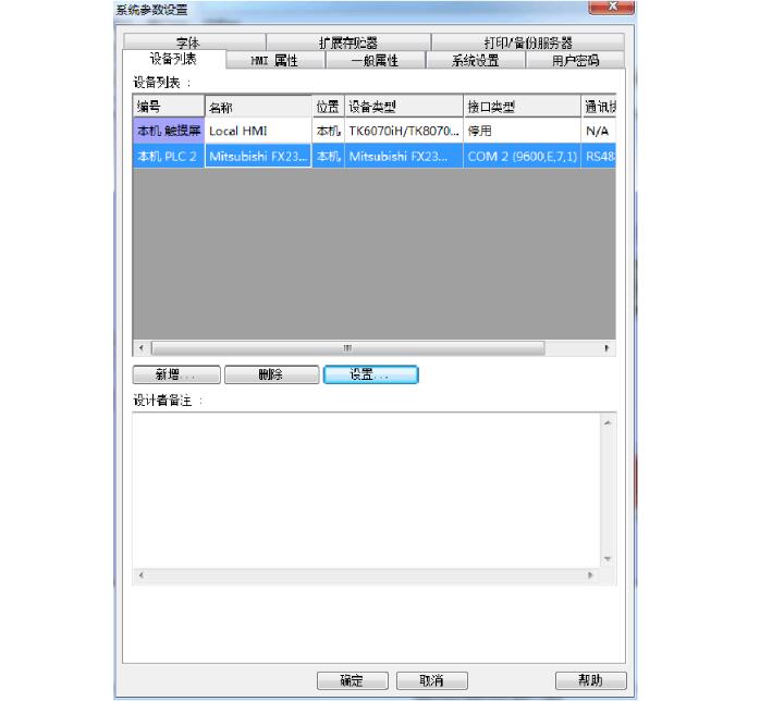
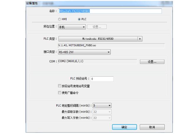
Weiluntong touch screen and Mitsubishi FX2N series PLC communication example1. Weiluntong touch screen settings:
2, PLC settings:
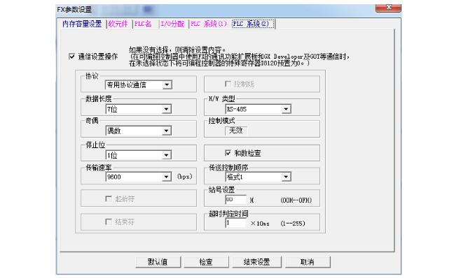
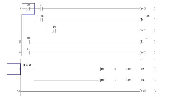
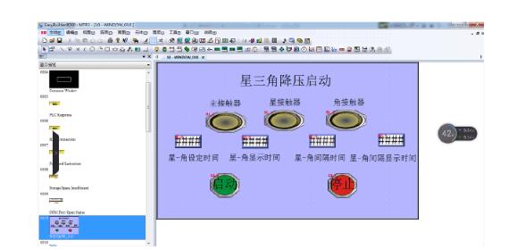
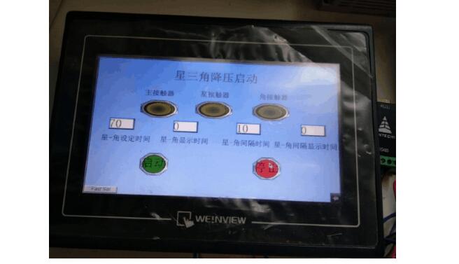
3, touch screen and Mitsubishi plc star triangle start instance:
PLC program:
Touch screen program:
wiring:
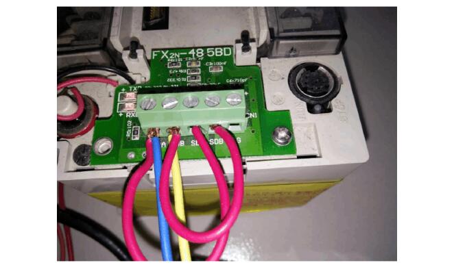
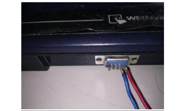
The terminal is used to facilitate the connection of wires. It is actually a piece of metal enclosed in insulating plastic. There are holes at both ends to insert wires. There are screws for fastening or loosening, such as two wires, sometimes Need to connect, sometimes need to be disconnected, then you can use the terminal to connect them, and can be disconnected at any time, without having to solder or twist them together, very convenient and fast.
Power Terminal Block,High Power Terminal Connector Block,Power Terminal Block Connector,Ac Power Terminal Block
Sichuan Xinlian electronic science and technology Company , https://www.sztmlch.com