Application background
In recent years, the world ’s demand for energy has been expanding, and energy as the foundation of a country ’s development has received increasing attention from all countries. Conflicts due to energy, especially oil, have continued. In order to ensure the supply of energy, in addition to actively looking for domestic oil fields, China is also actively looking for foreign supplies. Therefore, at present, China's oil supply tends to diversify. The transportation of oil is mainly carried out through oil pipelines, and oil transportation itself is an industrial process with huge energy consumption. How to find the lowest cost solution for different oil transportation under the current situation of oil diversification has become an important issue. The construction of large-caliber, multi-functional and highly automated oil test loops can obtain various data of oil storage and transportation in different environments, provide reliable and accurate test data for each storage and transportation station, and maximize oil storage and transportation. To reduce maintenance work during storage and transportation. To this end, China National Petroleum Pipeline Corporation established a large-scale, world-class oil pipeline test base in northern China.
In order to better meet the test requirements, it is required that the process flow can realize the shutdown and restart test. On the basis of the denaturation study and the wax test, the flexibility of process switching is increased as much as possible, and various tests can be conducted under various working conditions. . Through the optimized design of the process flow, the length of the test pipe section is increased and the test accuracy is improved. The data of the test loop are all automatically collected, and the detection equipment uses high-precision instruments. In order to meet the needs of other oil testing in the future, the crude oil unloading interface is reserved.
To this end, adopt the control mode with the operator workstation as the upper computer and the programmable controller (PLC) as the lower computer to form an automatic monitoring system. PLC adopts the advanced ControlLogix series products of American Rockwell Company, and uses Logix5000 programming to realize the functions of remote data collection, control of actuator operation, and fault detection of actuator; at the same time, it adopts dual PLC (CPU) operating mode to realize the control system The hot standby function; the host computer works in the Windows environment, uses the Citect industrial control configuration software of Australian Ci Technologic Company, which is widely used in engineering, to develop monitoring software, and adopts the interface of the two-person machine to realize the real-time dynamic display of the loop process process. Automatic data collection and processing, fault alarm, real-time, historical report printing and other functions; the use of ControlNet network for data exchange, online monitoring and display of the system equipment parameter values, to fully ensure the speed of information transmission. Therefore, it is possible to realize automatic monitoring and timely control of the operation of each device of the entire test loop.
ControlNet network structure
ControlNet is a deterministic and repeatable control network. Multiple controllers can coexist on the same link. Nodes on the network are in a peer-to-peer position and can be accessed from any node. The network bus rate is 5Mbps. Within a distance of 250m, the maximum number of nodes that the network can support is 48. The bus topology can be star, tree, bus, or any combination of the three. The number of repeaters that can be used is only limited by the delay time of the system. With repeaters, the maximum end-to-end transmission distance is 3km using coaxial cable, and 30Km using fiber optic transmission, and supports a redundant structure.
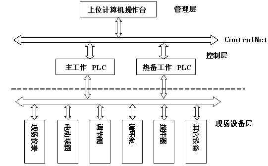
This system uses a three-layer structure: the management layer, the control layer, and the field device layer. The structure diagram is shown in Figure 1.

Figure 1 System structure diagram
In this system, the total length of the ControlNet network is 50m, and no repeater is used to ensure the real-time information. The upper computer uses the 1785-PCIC card to connect to the ControlNet network, and the lower PLC connects to the ControlNet network through the 1756-CNBR module. In order to ensure the reliability of the system, dual network redundancy and dual controller redundancy are adopted.
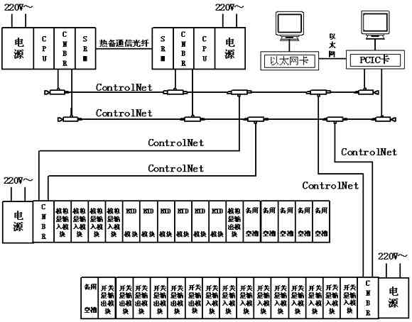
The control layer adopts ControlLogix series products from ROCKWELL, the main configuration is: 1756-L55M24, 1757-SRM, 1756-PA75, 1756-A4, 1756-CNBR, 1756-A17, 1756-N2, 1756-IF16, 1756-IB16 , 1756-OW16I, 1756-IR6I, 1756-OF8, etc. These devices constitute dual redundant control stations and remote I / O stations.
The field equipment layer should meet the various data collection needs and process control functions of the test loop. The main configuration is: 16 electric ball valves, 7 electric gate valves, 1 inverter, 1 agitator, and pressure collection (4-20mA) 10 Point, differential pressure acquisition (4 ~ 20 mA) 2 points, temperature acquisition (4 ~ 20 mA) 66 points, liquid level acquisition (4 ~ 20 mA) 1 point, flow rate acquisition (4 ~ 20 mA) 2 points.
The overall composition of the system is shown in Figure 2.

Figure 2 System composition
Network configuration and communication
The configuration and management of the network use RSNetWorx for ControlNet software, which provides the design, configuration and management of the ControlNet network. RSNetWorx allows you to maximize the production capacity of the ControlNett network equipment you own, and quickly set up the equipment on the network through a simple software interface. These settings can be made in the "offline" mode by "drag / drop" the device icon. The operation will not be repeated here.
RSLinx gateway is used to realize the communication between the upper layer 1785-PCIC card and the control station and remote I / O station. RSLinx gateway includes the functions of OPC and DDE, as well as the function of PLC and other device data viewing. One RSLinx installed The computer acts as a gateway to access the control station and remote I / O station. RSLinx is an essential software for remote access. At the same time, the OPC function of RSLinx also makes it possible for the upper computer monitoring software to access the control station and remote I / O station. Its operation can be automatically scanned under the "online" condition, and will not be repeated here.
Realization of upper and lower communication
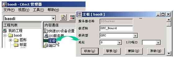
The upper layer monitoring software Citect and the control layer RSLinx gateway in this system both support the OPC function, so the communication between the upper layer monitoring software and the lower ControlNet network is realized through OPC technology. After using RSLinx to implement ControlNet network communication, the OPC should be set in the Citect software, and the I / O server, motherboard, port, I / O device, and variable label must be set in sequence. Figures 3 and 4 below are the system. The setting screens of the I / O server and main board in the middle, and other settings are no longer given.
Conclusion
After the system is put into operation on site, the operation is reliable and the effect is very good. It meets the requirements of the initial design. It can test various parameters of crude oil very well. The relevant software and measured parameters can be used to calculate the best crude oil transportation. Conditions, and can simulate the operation of real oil pipelines, forming a powerful field test loop.
The author of this article is innovative: build a simplified three-layer network architecture with ControlNet as the core; OPC technology is used between CTIect SCADA and ControlLogix series PLC, and the communication speed is improved; automatic data collection and process control of the test loop; multi-process Integrated control of the process.

Figure 3 I / O server settings

Figure 4 motherboard settings
As of September 2007, this project has produced economic benefits of 200,000 yuan. As the application progresses, the benefits will continue to increase. Data source: Baodi Project Team, Beihua Aerospace Institute of Technology.
The bulbs are installed inside of a vehicle. There are many different types of interior bulb. Interior lights for indoor lighting are usually installed in the center of the car interior. It's better to light up the car interior evenly. In addition, the light switch (SW) should be operated on both front and rear seats at the time of layout. SW generally has ON, OFF, and door linkage 3 locations. In order to reduce the thickness of the lamp, 5-10w bulb bulbs are usually used. To meet the illumination requirement of capacious indoor, the power of the bulb that uses is commonly 8~30W. The original reading light in the car is designed to read the map. In order to drive the driver, read the light and light up to the point, only on the required part. The rear reading lamp is the rear seat special reading light, with a larger point light illumination. Be careful not to give the driver and other passengers a sense of vertigo. The light can be connected to the door and switch. When the door is open, the lamp is mounted on the door to illuminate the foot part of the room and the outside foot. In order to give the signal to the back of the car, the installation position should be considered. The lamp has no special switch, but is connected with the door.
Auto Interior Lamp Bulb
Auto Interior Lamp Bulb,Car LED Auto Light,LED Reading Light,Interior Dome Light
Heshan Jianhao Lighting Industrial Co., Ltd. , https://www.sunclubtw.com