Regardless of your end application, reliability will be one of the main considerations in design. There are many ways to achieve reliability.
When considering design reliability, most engineers focus on a comprehensive metric: mean time between failures. In fact, Mean Time Between Failure (MTBF) is one of the important parameters for evaluating design reliability. But another parameter, "success probability," is equally important. Therefore, in order to finally introduce a reliable design, designers should consider other factors and ensure accurate reliability analysis.
Reliability is essential no matter which product you design, although the reasons are different, but it depends on the end application. Aerospace and military designers must ensure the safety of operators/passengers and ensure successful completion of tasks. In the telecommunications field, the goal of reliability is to prevent service disruptions, as this can affect revenue streams and reputation. The task of the industrial and process control engineers is to minimize downtime and ensure safe, trouble-free operation in the event of a failure. For commercial applications, designers must ensure that their products do not experience any problems during the specified warranty period.
Using FPGAs, you can develop more integrated solutions that extend the system's mean time between failures. This is even more apparent when device manufacturers regularly provide quarterly reliability reports, as Xilinx does, and its quarterly reliability report is called UG116.
At the highest level, reliability can be considered from two perspectives. First, the credibility of the system to operate smoothly within the specified service life. This can be done with MTBF, probability of success, and familiar bathtub curves. Second, when an error event occurs, how to ensure that your design can continue to work and remain trouble-free, or report on unresolved issues. The way our engineers conduct design and analysis can affect both of these aspects of reliability.
To ensure the reliability of your solution, your development environment must establish a proper engineering governance system, set up review gates, design rules and guidelines, and arrange for peers to conduct independent reviews at appropriate points throughout the lifecycle.
MTBF and bathtub curveMTBF is defined to predict the time between failures in the system from a statistical perspective. The manufacturer calculates the MTBF from the reciprocal of the failure rate of each component. We generally refer to these failure rates as FIT rates, where the failure time (FIT) is 1e-9 hours-1. You can request a failure rate from the component supplier and can also be calculated according to the military manual MIL-HDBK-217F or the Bell-core/Telcordia SR332 standard. The relationship between MTBF and FIT rate is as follows:
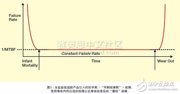
However, the above failure rate is only valid for a constant failure rate period in the bathtub curve, as shown in FIG.
The bathtub curve depicts an early ("early failure period") failure when the product was introduced, a failure that occurred during normal service life ("constant failure rate"), and a failure at the end of the product design life. Therefore, in the production process, some form of "aging test" is usually performed to eliminate early failure period failure. During the aging test, potential defects of the device are accelerated under various temperatures, which ensures that the device fails before being delivered and loaded into the system.
You can use the Weber distribution, or life data and analysis to determine the location of your product or system in the tub, which is easy to do with Excel. The shape parameter β indicates whether the failure rate is stable, increasing or decreasing. If the shape parameter (β) is less than 1.0, it indicates that the failure rate is decreasing during the early failure period. If the shape parameter is greater than 1.0, the failure rate is rising, and this phenomenon will occur during the wear phase.
To ensure a successful probability of success, many products require MTBF to be much higher than expected.
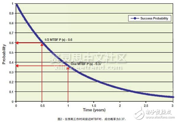
Once you have determined your position in the bathtub curve, it is understandable that you can continue to operate without problems during at least MTBF. However, this is not the case. MTBF is a statistical description of the failure rate that a product may have over its useful life; it does not refer to the expected life of the product. If you want to get the expected life of the product, we need to consider the probability of success obtained by the following formula, where t is the expected working time (unit: hour).
After plotting the probability of success as a graph, it can be seen that when the expected working time is close to MTBF, the probability of success is about 0.37, as shown in Figure 2. This means that the single module of success probability is still valid after the time taken for the MTBF to reach 0.37. If a batch of devices is considered, 37% of them still work.
Therefore, in order to ensure a successful probability of success within the working life, many systems/products require that the MTBF must be much higher than the expected lifetime. For example, assuming a five-year lifetime with a probability of success of 0.99, the MTBF required for the product must reach 4,361,048 hours or 497 years, as shown in the following equation.
Obviously, this far exceeds the service life.
Reliability calculationYou can calculate reliability and MTBF—part count analysis or part stress analysis—in one of the following ways. The part count analysis is relatively simple, and can sometimes be carried out early in the development cycle as one of the indicators for whether the product meets the reliability requirements. This type of analysis takes into account the level of quality of parts, the quantity, and the environment in which they are used. Part count analysis can be done quickly. However, the results tend to be conservative, resulting in an increase in failure rate and a shortened MTBF.


Part stress analysis will take into account more parameters and therefore take longer, but the results of such analysis are more accurate. Stress analysis takes into account many factors such as temperature, electrical stress, quality, structure, and working environment, depending on the type of component you are analyzing. For current applications, the failure rate obtained by such analysis is much more accurate.
Pressure Type Liquid Level Sensor
It is suitable for liquid level measurement of various media in petrochemical, metallurgy, electric power, pharmaceutical, water supply and drainage, environmental protection and other systems and industries. The exquisite structure, simple adjustment and flexible installation provide convenience for users to use easily. Standard signal output modes such as 4 ~ 20mA, 0 ~ 5V and 0 ~ 10mA are optional by the user according to needs. Using the principle of hydrostatics to measure liquid level is an important application of pressure sensor. The special cable with ventilation duct in the middle and special sealing technology are adopted, which not only ensures the water tightness of the sensor, but also connects the reference pressure chamber with the ambient pressure, so as to ensure the high precision and high stability of the measurement.
Pressure Type Liquid Level Sensor,Liquid Water Level Sensor,Liquid Level Mearurement Sensor,New Pressure Type Liquid Level Sensor
Taizhou Jiabo Instrument Technology Co., Ltd. , https://www.taizhoujiabo.com