Research Background Traditionally, the test method of the LC resonant frequency is to change the frequency of the signal applied to the (directly or indirectly) LC resonant tank point by point to find the frequency point at the time of maximum output, and this frequency point is defined as the LC resonant frequency. Obviously, the disadvantages of this test method are: the test method is complex, the test time is long, the test accuracy is low, and it is directly affected by the temperature change caused by the resonant body, especially the magnetic core resonant body, due to the long test time. The principle and method of testing the LC resonant frequency based on the PLL in this paper is fast, high-precision, and free from the influence of temperature change, and it also has the characteristics of simple test method. This thesis mainly uses the theory of PLL to test the LC resonant frequency.
Fundamentals The test of the LC resonant frequency can be done in the form of a 2nd coupling loop as shown in Figure 1. Among them L2C2 makes up one LC resonant circuit to be measured, L1 is the transmitting coil, Li is the receiving coil that only has a single turn. The general test can satisfy: 1/ωCi "Ri" ω Li, M2 "M1" M3 test conditions. Here ω is the actual working angular frequency, Ri, Ci and R1, C1 are the circuit parameters of the receiving loop of the receiving coil and the transmitting coil respectively, M2 is the coupling coefficient of the LC resonant tank to be measured and the receiving coil, and M1 is the LC to be measured. The coupling coefficient between the resonant circuit and the transmitting coil, M3 is the coupling coefficient between the transmitting coil and the receiving coil. Satisfying the above test conditions can be drawn from Figure 1.

Here V1 is the voltage of the transmitted signal and V2 is the voltage of the received signal. The transfer function of the test loop is determined by the following equation.

Figure 1 Schematic of the LC resonant test circuit

According to the nature of the LC resonant tank you get:
Here, ω 01 and ω 02 (ω 02 â€Ï‰ 01 ) are the resonance angle frequencies of the LC resonant tank of the transmitting coil and the LC resonant tank to be measured, respectively. In practical applications, Q 2 is about 100, and Q 1 is less than 1. At this point, Equation 3 can be simplified as:
The composition. among them:
If the angular frequency difference Δω between the actual working angular frequency and the resonance angular frequency to be measured is controlled to be much smaller than ω02, this can ignore the higher order terms of Δω, and Equation 5 can be further simplified.
Therefore, the amplitude function and the phase function can be simplified as follows.
The amplitude at resonance is maximum, and the amplitude and phase functions can be given by the following equation.
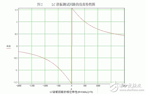
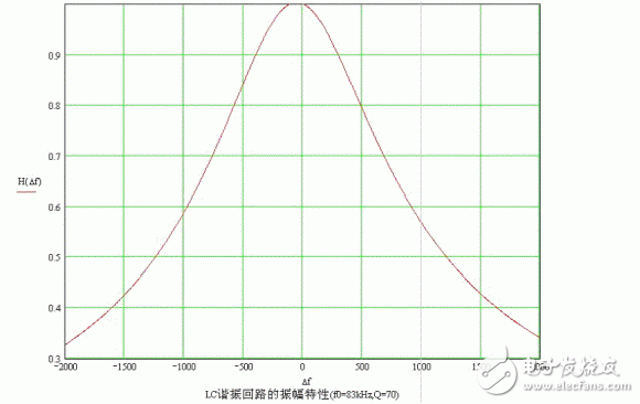
Set the circuit parameters as f02=83kHz, f01=800Hz, Q1=0.1, Q2=70, M2/L2=0.2, M1/L1=0.1, M1/L2=10-4, R2/Ri=10-3. The simulation results under Mathcad are shown in Fig. 2, where the amplitude characteristic is the normalized characteristic and d = Δf. It can be seen from the figure that there is a jump-around phenomenon, which is caused by the occurrence of zeroing in the denominator part of the formula. The difference in the angular frequency of this point is defined as Δω0, then the following relational expression can be obtained from Equation 8.
The above equation satisfies the PLL operating conditions, that is, the PLL loop using the above noted phase signal is finally locked at the resonant frequency of the LC loop to be measured. In actual use, according to the test conditions, it is easy to achieve A, B "1. The loop sensitivity formed by Fig. 1 is:
The decision [2]. So even if there is a considerable change in ω02, the change in θ 0 is small, ie θ 0 can be considered as a constant. In the following, we only discuss the operation of the PLL when its operating range is near the resonant corner frequency. Then formula 8 makes the following changes.
Use Equation 10 to compensate for the phase. After compensation, the actual phase Δθ of Equation 8 is:


The compensation method can generally use a two-way delay circuit. Since the actual application uses a fixed delay loop, an error between the measured resonant frequency and the true resonant angular frequency is assumed, assuming that the resonant angular frequency difference is Δω02, and the working angular frequency range satisfies Δω “ω 02 . Assuming that the phase of the real required compensation is determined by Equation 10, then a phase difference Δθ0 is generated with the fixed phase compensation, then Equation 10 can obtain the following relational expression.
Here Δω 02 is the difference in resonant frequency due to a fixed delay when the PLL loop is operating in a locked state, which is a constant for a particular LC resonant tank. When the test conditions are met, even the introduction of a fixed phase to compensate for the resulting error is small and can be almost negligible.
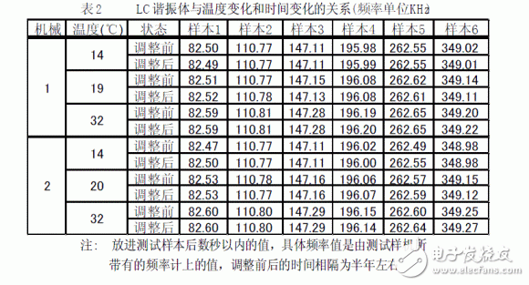
Example According to the principle introduced in this article, an LC resonant frequency tester was used to test six types of LC resonant body samples (products). The LC resonance tester has been applied to the production and product inspection of six types of LC resonators. The specific results are shown in Tables 1 and 2.


Conclusions This paper presents a fast, high-precision, and temperature-independent test of the LC resonant frequency principle. The validity of the above principle is verified by specific examples. It is used as a research topic in the future how to solve emission problems. The operating characteristics of the PLL are different between the PLL operating characteristics and the transmitting and receiving terminals in the same frequency state and the receiving end.
Mc4 Connector Extension Cable,Solar Panel Wire 10 Awg,Pv Extension Wire,Optical Ground Wire
Sowell Electric CO., LTD. , https://www.sowellsolar.com