Tl431 is produced by Texas Instruments, a tl431 is a three-terminal adjustable shunt reference with good thermal stability. Its output voltage can be arbitrarily set to any value from Vref (2.5V) to 36V with two resistors. The device's typical dynamic impedance is 0.2Ω, which can be used in many applications to replace Zener diodes, such as digital voltmeters, op amp circuits, adjustable voltage supplies, switching power supplies, and more.
How to identify the A, K, and R poles of tl431:
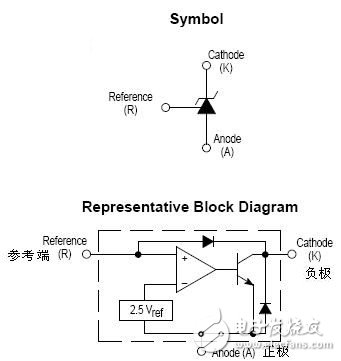
The symbol of tl43l is shown in the figure above. It has three poles A, R and K respectively, and some schematics mark A, K and G. A and K are the positive and negative terminals of the Zener diode, respectively, and the R pole is the sampling end.
1. Determine the method of A and K poles. According to the schematic diagram, the A and K poles can be judged by measuring the diode with a multimeter. When measuring, the range is placed in the RX1K block. When the black pen is connected to the A pole and the red pen is connected to the K pole ', the resistance is turned on (the resistance of the ordinary silicon diode), and the meter is interchanged. If the resistance is infinite, the conduction can be determined. In the state, the foot connected to the black pen is the A pole and the other foot is the K pole.
2. Determine the method of the R pole. Set the multimeter's range to RxlOk, the black pen to the K pole, and the red pen to the A pole. At this point, the meter should have no indication. When one hand touches the black pen and the other hand touches the R pole, the pointer should swing greatly. When this condition is met, the foot touched by the hand is the R pole.
Positive and negative resistance between the poles of tl431 under normal conditions1. Measurement of the forward and reverse resistance of the Zener diode.
The multimeter's range is set to Rxlk block, the black pen is connected to the A pole, and the red pen is connected to the K pole. At this point, the voltage is measured {the forward resistance of the diode. Measure the reverse resistance elbow and the range should be set to Rxlk. The data measured with the MF47 type meter is: forward resistance 6xlkΩ; reverse resistance ∞.
2, R pole and A, K pole positive and negative resistance measurement.
The multimeter range is set to Rxlk block, the black pen is connected to the R pole, the red pen is connected to the A pole, and the resistance should be 35xlkΩ. The interchangeable test pen should have a resistance of lOxlkn. The black pen is connected to the R pole, the red pen is connected to the K pole, and the resistance should be 11 & TImes; lkΩ; interchange the test leads, the resistance ∞.
3, K pole and A, G pole positive and negative resistance measurement. The multimeter range is set to Rxlk block, the black pen is connected to the K pole, the red pen is connected to the R pole, and the resistance is ∞; the interchangeable test pen, the resistance should be 11 & TImes; lkΩ. The black pen is connected to the K pole, the red pen is connected to the A pole, and the resistance is ∞: the interchange meter is used, and the resistance is 8xlkΩ.
Power up test tl431
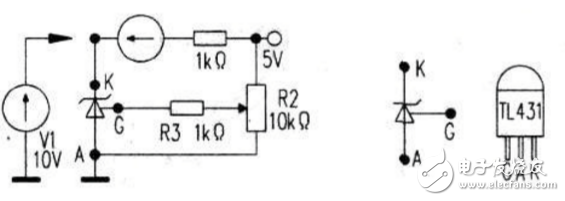
The figure above is the circuit tested by tl431. The power supply is 0~20V maintenance power supply. An ammeter is connected between the K-pole and the power supply to clearly observe the change of the K-pole current caused by the voltage change of the R-pole. By connecting a voltmeter between K and A, it is possible to clearly observe the change of the output of tl431 with the power supply. Before the test, adjust the potentiometer to the vicinity of the intermediate value. Using the victory 89B digital meter to measure the K pole to ground voltage, adjust the voltage output of the maintenance power supply, and find that the voltage of the K pole to ground has only two states, one is about 2V (low level); the other is equal to the power supply voltage (high) Level).
Judgment of normal or not. For the online TLA31 power supply error comparator, an external maintenance power supply can be used for detection. Connect the repair power supply to the sampling point of tl431 when the voltage is adjusted to be higher than the nominal voltage. Tl431 is on. The K pole voltage is low. That is, when the power supply voltage rises, tl431 turns on, the diode of the photocoupler is turned on, so that the triode is in a saturated state, and finally the time for controlling the conduction of the primary power switch tube is shortened (reducing the duty ratio), so that the output The voltage is reduced. If the maintenance voltage is lowered. Tl431 is closed. The K-pole voltage is high, and the diode of the optocoupler is turned off, so that the triode is in the off state, and finally the time of controlling the conduction of the power switch of the primary of the transformer is increased (increasing the duty ratio). Increase the output voltage. The closed-loop voltage regulator circuit of the switching regulator power supply uses the tl431 to turn on or off the two states to adjust the duty cycle of the switch tube to control the output voltage to be stable. When the multimeter is measured, if the resistance between the poles of lC is normal, it can be judged that tl431 is normal: when using the maintenance power supply to test the power. In the case of changing the power supply voltage, if tl431K has two levels of high and low changes to the ground, it can be judged that tl431 is normal.
Tl431 replacement plan:If the tl431 damage is damaged, if it is not replaced by the same model, it can be replaced with KA431, μA431, LM431, YL431, S431, etc. (The resistance is 0)
Tl431 suffix letters indicate product grade and operating temperature range C is commercial (-10 ° C ~ +70 ° C),
I is an industrial product (-40 ° C ~ +85 ° C), M is a military product (-55 ° C ~ +125 ° C).
Bluetooth Speaker,Outdoor Bluetooth Speaker,Hifi Bluetooth Speaker,Round Bluetooth Speaker
Comcn Electronics Limited , https://www.comencnspeaker.com