In the 1960s, the automotive industry turned its attention to finding innovative ways to keep drivers and passengers safe. What is the result? Buffer steering and dashboards, seat belts, and subsequent airbags and electronic stability control systems have emerged. Since then, automotive engineers have been exploring ways to protect the safety of pedestrians, drivers and passengers. As a result, the automotive industry has made great strides in improving safety, from anti-lock braking and multiple airbags to rearview camera systems and advanced navigation systems.
This article refers to the address: http://
Today, the automotive industry continues to be under pressure from governments, NGOs and consumers to create safer vehicles. For example, the National Highway Traffic Safety Administration (NHTSA) has specified that the driver must be able to see the rear area of ​​the vehicle when reversing. It is expected that all passenger cars sold in the United States will adopt this proposal in order to significantly reduce the disasters and casualties caused by reversing accidents involving children, the disabled, the elderly and other pedestrians.
Therefore, the camera-based vision system is the key to implementing this proposal. National Highway Traffic Safety Administration requires that all vehicles manufactured in the United States on or after September 1, 2014 must have a rear view system. This requirement is driving the growth of camera solutions, driving the industry to develop higher performance, better resolution imaging solutions and driving the next generation of security applications and security systems.
Camera for the emerging automotive market
In the automotive industry, cameras are becoming an important part of the Advanced Driver Assistance System (ADDAS). These cameras are used for a variety of purposes such as traffic sign recognition, rear view systems for parking distance control (PDC) and lane departure warning systems (LDW). Today, many new vehicles integrate several cameras that cover all areas around the car, enabling an optimized safety system.
In these advanced automotive camera security systems, enhanced imaging and sensing capabilities open up an infinite world of possibilities. The camera vision system uses a far-field field to complement the long-range radar, and uses a wider field of view to compensate for the short-range radar or ultrasonic sensor, so that the driver can see the front and rear roads. Therefore, another set of data can be provided to confirm the accuracy of the overall picture drawn. For example, support data from radar and cameras can greatly enhance confidence in decision making, such as the use of brake systems.
Table 1: Requirements for car cameras
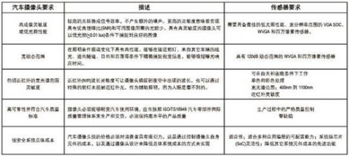
Image sensor in car camera security system
Since the advent of charge-coupled devices (CCDs) in 1969, their applications have grown to include digital cameras, telescopes, cameras, scanners, and other imaging applications. However, CCD has its inherent shortcomings in automotive safety applications. The most obvious is that CCD manufacturing requires specialized factories, equipment and processes, which makes it difficult to produce automotive cameras at low cost and in large quantities. In terms of car safety, the CCD architecture also has inherent limitations. Standard CCD image sensors are designed to read data in a serial manner, which means that all subsequent pixels must be read before the subsequent pixels can be read. This limits the frame rate or the number of images read per second, and is an important drawback in automotive safety applications where fast capture of images is a critical feature. In addition, most CCD cameras do not have the necessary wide dynamic range (WDR) capabilities highlighted in Table 1.
A complementary metal oxide semiconductor (CMOS) image sensor is an alternative solution that can be produced at cost-effective commercial foundries using the same high-volume production process as other computing chips. The CMOS image sensor has a random access read function, which means that pixels can be randomly addressed, and a sub-frame, that is, an area of ​​interest, can be quickly read. Therefore, CMOS image sensors overcome some of the shortcomings of the above-described CCD sensors, and have almost unlimited sub-sampling and sub-window capabilities. An additional advantage of CMOS cameras is the ability to meet wide dynamic range (WDR) and low illumination performance requirements, further driving CMOS image sensors to replace CCD sensors and becoming the preferred sensor for many imaging markets, including the automotive market (see Figure 1). In fact, the CMOS automotive sensor market is expected to grow from less than 10 million in 2009 to more than 50 million in 2017 (IMS 2009 Automotive Market Report).
In a vehicle with a camera security system, an image sensor is used to complete scene observation or scene processing.
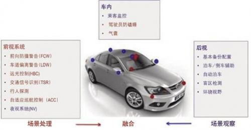
Figure 1 CMOS image sensor in automotive applications
Scene observation
Scene viewing applications typically output on video displays include rearview cameras, multi-camera 360-degree field of view, assisted parking, alternative rearview mirrors, night vision, and rear passenger surveillance. In these applications, key image sensor requirements include excellent low-light performance, WDR, and low-power operation while meeting automotive quality standards and low unit cost in high-volume production.
Aptina Imaging is a model for CMOS image sensor suppliers, offering a fully integrated imaging solution for scene viewing applications. For example, VGA system-on-chips (MT9V128 and MT9V129) designed for automotive scene observation systems, and advanced megapixel (MT9M024) solutions for next-generation vision cameras.
Scene processing
In a scene processing application, the processing unit uses the output of the imager to send an alert or make decisions regarding vehicle operation, including lane departure warning, traffic sign detection, rain detection, headlight dimming, and blind spot detection.
Using these intelligent security systems, the processing computer receives data from the sensors, makes decisions, and sends commands to the vehicle subsystem to prevent accidents, mitigate the severity of the accident, or protect the owner. For example, the processing computer may use data from the image sensor to determine an impending collision and issue an instruction to the vehicle subsystem to take braking action.
Technological advances in microprocessors and image sensors have made intelligent security systems a reality. As technology advances faster, more intelligent image sensors will become part of a passive and active safety system.

Figure 2 Multi-camera 360 degree / surround vision system topology
Future support for car safety
Emerging automotive camera security applications are growing at an alarming rate, and the placement rate of these applications has been rising. Regional standards, traffic conditions, and driver preferences determine the features available. For example, cars sold in the United States have rear-view cameras, lane departure warnings, and 360-degree surround vision. European drivers, in addition to 360-degree surround vision cameras, can also enjoy rear-view cameras, lane departure warnings, and automatic high beam control. Night vision and traffic sign recognition require up to eight or more cameras per vehicle.
As the functionality and number of cameras in each car increase, providing flexibility to integrate new features and interfaces is important for image sensor manufacturers. Whether using a collaborative chip approach within the camera module or within an electronic control unit (ECU), the best approach is to separate the sensor and image sensor processing ISP functions.
Image sensor manufacturers are working hard to increase resolution from VGA to megapixels. Higher resolutions allow for sharper corners and edges. Of course, it is also necessary to control the power consumption and cost of the system to minimize the power consumption of the camera module while achieving the best image quality. One way to reduce costs is to use sensors that can be used for both scene observation and scene processing applications. This requires multiplexing the output of the sensor between scene observations primarily for display and scene processing occurring in the ECU, depending on system architecture, interface, and application conditions. Aptina Imaging has developed a solution to these challenges by providing a megapixel sensor and a synergistic chip solution for camera modules and ECUs while achieving lower power consumption and greater flexibility.
in conclusion
The automotive industry continues to be under increasing pressure to produce safer vehicles. Today, camera vision systems have become the key to developing more advanced security systems. In these systems, CMOS image sensors not only meet WDR and low-light performance requirements, but also provide economies of scale that are critical to the price-sensitive automotive market, helping to achieve significant growth in this area.
Led Curtain Display is a creative design and upgrade version of outdoor led display& screens. this Led Strip Curtain series of products have features of light weight, energy-saving, high transparency, fast installation and easy maintenance. With advanced and top level of led diode from LightKing, PrivaLed's outdoor curtain LED displays have low power consumption and high brightness. In this ways, It is very stable and durable during lifetime.
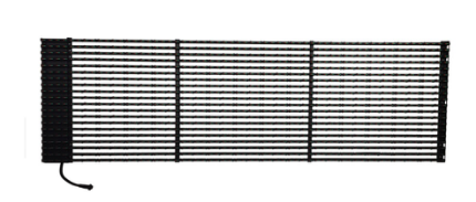
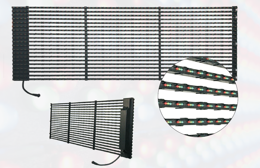
For better understanding Led curtain display main advantages,
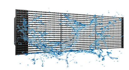
High Water-Proof grade applied with IP65 water-proof standard, make your screen working perfectly without problems even in heavy rain.
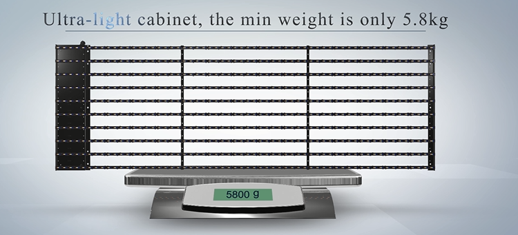
Light-weight cabinet The cabinet is about 5-8 KG per square meter, 60% less weight compared with traditional tile and have greatly reduce the load bearing pressure of the structures.
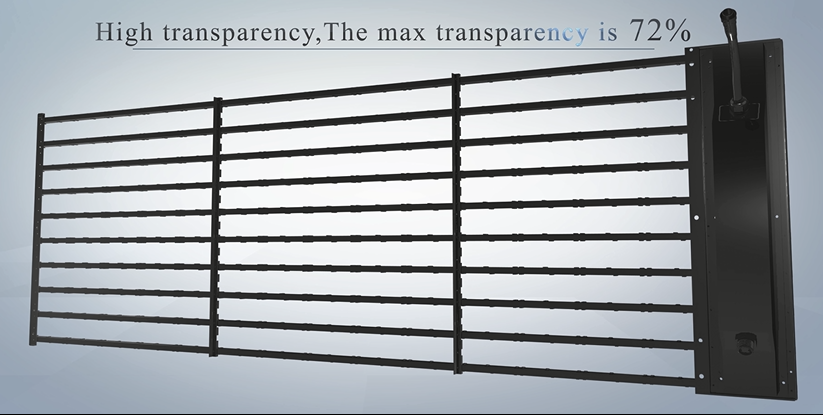
High transparency rate Louver design, make the transparency rate up to 72%, and this design greatly satisfied people`s curiosity to see outside from inside.
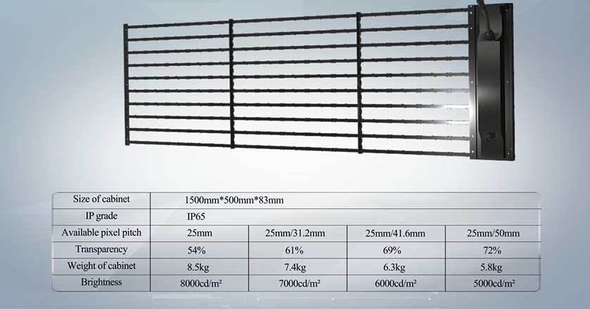
High brightness8000nits for P25, could be used absolutely for outdoor under strong sunshine.
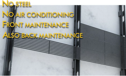
Fast & easy installation No need steel structure, Solid and simple assemble style, make installation and maintenance quick and easy. It stands firmly even in big wind.
Installation Steps
Installation Steps
1 Fitting the steel structure: fitting it on the wall firmly
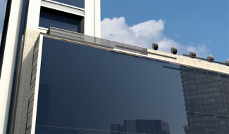
2 Attach the U-Tile frame to the structure firmly
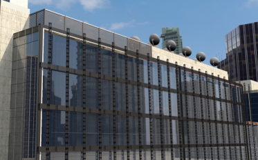
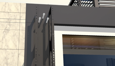
3Lock the frame on the structure by screws
4Hanging the upper right hooks of the cabinet to the card slot of the right U-tile Frame.
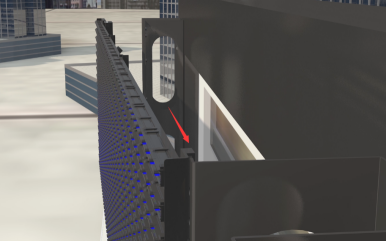
5
Buckle the left position pins of the cabinet to the location holes of the left side of the U-tile frame
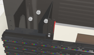
6 Aim at the screw holes for the front service installation, fitting 6 screws on the U-tile frame through the cabinet from the front.
(This is a procedure of front service, this cabinet support also available for back maintenance)
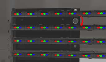
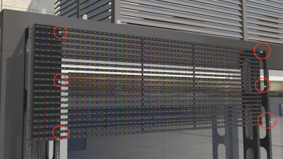
7 Then finished installation for one cabinet. The same as the next cabinet.
8 Cable Connection.
Connect the male-plug (with cable) of the next cabinet to the female-plug of its upper cabinet firmly.
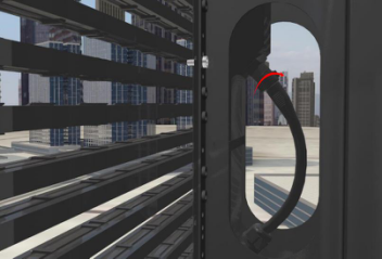
9 Using the same mode to finish the rest connection (five-pins cable), then the installation work for a complete LED display is finished.
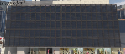
After-sale maintenance
1 The cabinet support single trip maintenance. If there any bad LED lamp or damage on single strip, you can remove the strip separately without take out the cabinet and control box.
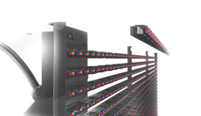
2, Cabinet support front & back installation and maintenance. If there any problem on single cabinet, you can remove the cabinet from the front & back of the screen.
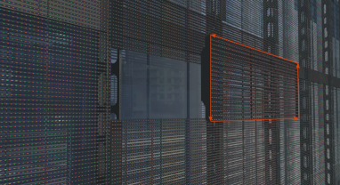
3 ,If there damages on the control box, you need remove the cabinet and open the cover of the power supply box to do repair & exchange work.
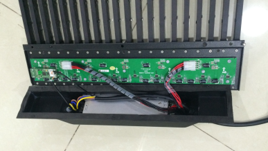
Cabinet size:

Package: Wooden case 1 for 10 led strip curtain cabinets.
Package size:
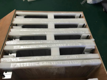
This outdoor LED Strip curtain display series product are widely used for building facade, behind of glass wall, in front of glass wall, led billboard& signs and on top of building.
Welcome to visit our factory in Nansha Guangzhou China. Please contact us for any questions or inquiries!
Led curtain display Parameter
Model number
Pixel pitch
Pixel configuration
Size of block module
Resolution of module
Density
Cabinet material
Size of cabinet(l*h*t)
Weight of cabinet
Driving method
Best viewing angle
Max power consumption
Colors
Gray scale
Color temperature
Control method
Driving device
Frame frequency
Refresh frequency
Brightness
Working voltage
Working temperature
Out-of control point
Brightness Control
IP grade
Mtbf
Transparency
LED Curtain Display
Led Curtain Display,Outdoor Led Curtain For Building,Led Curtain Wall Display,Led Strip Curtain
Shenzhen Priva Tech Co., Ltd. , https://www.privaled.com