Over time, the use model of portable device audio amplification circuits has been greatly developed. Recently, cellular phones and other portable electronic products have integrated handsets, earphone speakers, and near-field speakers (for hands-free operation). In addition, reproducing music (MP3 files) and movie channels also impose a heavy burden on the audio channel. As a result, the power consumption of the audio channel is no longer a branch problem, but becomes the main channel for power leakage. Moreover, low-fidelity sound reproduction has become a thing of the past, and today's audio transmission requires a signal-to-noise ratio of 100 dB or more and a total harmonic distortion of less than 0.1%.
Headphone Amplifier
Acoustic audio power amplifiers are generally divided into two types of operation: headphone amplifiers (HPA) and speaker amplifiers (SPA). Headphone amplifiers must drive 32Ω or 16Ω speakers up to 30mW and maintain very high audio quality (typically 105dB SNR, 0.01% THD and 20kHz bandwidth). However, for headset applications, 30mW is a very high output power that is high enough to cause pain. Typical listening levels are between 100μW and 1mW.
Producing 30mW of power on a 32Ω load requires a peak signal swing of 1.4V, while also preparing an extra margin for the IR drop. Therefore, a supply voltage of ±1.8V is usually used to achieve an output power of 30mW.
A typical headphone cable consists of three: two for the left and right drive signals and the other for the common return ground. In addition, additional lines may need to be added for volume control, mute, or microphone output. In this configuration, the stereo headphone amplifier must have a single-ended output.
However, if the power supply uses a single voltage rail, this will result in a large DC offset problem. To avoid the use of large AC-coupling capacitors, most headphone amplifiers are powered by a separate power supply, which typically uses an on-chip inverter charge pump to generate a negative voltage rail.
Most headphone amplifiers use linear amplifiers (for example, variants of the A/B type of output stage) to achieve the high quality audio performance required by headphone amplifiers. Traditional A/B amplifiers consist of Class A and Class B modes of operation (Figure 1). These amplifiers are typically designed to operate primarily in Class A at low output power. Class A states provide the best audio performance due to the low crossover distortion.

1: Class A (a), B (b) and A/B (c) linear amplifier designs with common output stage configurations
The Class B mode of operation is effective at high output levels, when it has higher efficiency than Class A. However, the Class B mode of operation has higher crossover distortion. In summary, Class A/B amplifiers can achieve very low total harmonic distortion because most of the crossover distortion can be attenuated by closed loop feedback.
Under constant supply conditions, the A/B class amplifier efficiency is proportional to the output voltage swing. In order to recover the efficiency loss at low output power, the "G-type operating mode" technique can be used to reduce the voltage rail value at low level signals.
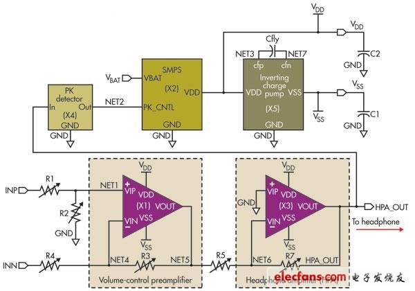
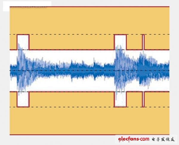
A circuit is needed to detect the input signal level. If the level exceeds a predetermined threshold, the voltage rail can be raised to a higher value as needed. Most Class G amplifiers have two voltage rail values: one for the high rail value of the large signal swing (VDD) and one for the low level signal with only a small portion of VDD (such as 1/2 of VDD). Low rail value (Figure 2). Thus, the signal efficiency at 1/4 of full-scale output power is approximately equal to the efficiency of the full-scale power signal (Figure 3).

Figure 2: Class G headphone amplifier (with separate power supply) helps to recover efficiency losses at low output power

Figure 3: In Class G headphone amplifier operation, the signal efficiency of 1/4 full-scale output power is approximately equal to the power of the full-scale power signal.
Here, the signal level drives two voltage rail values
U-1000 R2V/XV/RV Cable
Standard: NF C 32-321, C32-321/A1 IEC 60502
Rated Voltage: 0.6/1kV
Others: Fire Cable and other property Low Voltage Power Cable can be available
Applications: Those LV Power Cables used for electricity supply in fixed installation, power networks,underground and in cable ducting where where mechanical damages are not to be expected.
N2Xsy R2V Power Cable,12 Kv Cable,Insulated Copper Wire,Enameled Copper Wire
Shenzhen Bendakang Cables Holding Co., Ltd , https://www.bdkcables.com