Abstract: Introduce the CAN bus and its communication protocol J1939, and design the hardware structure of the multi-ECN communication platform based on the CAN bus; elaborate the software design method of node ECN communication, and realize the function of data communication under the condition of simulation experiment. Tests show that the platform is stable and reliable.
introduction
With the wide application of integrated circuits and single-chip microcomputers in automobiles, the number of electronic controllers on modern automobiles is increasing. Common electronic fuel injection devices for engines, anti-lock braking devices (ABS), and airbag devices are common. , Electric door and window device, active suspension, etc. Although the increase of the electronic control system improves the power, economy and comfort of the car, the accompanying complicated circuit also reduces the reliability of the car and increases the difficulty of maintenance. From the perspective of wiring, most of the traditional electronic gas systems use a single point-to-point communication method, and there is little contact with each other, which will inevitably cause a large wiring system. Therefore, a new concept-CAN, the electronic controller area network on the car, came into being. In order for parts produced by different manufacturers to work in the same car, standards must be established. According to the relevant ISO standards, the topology of CAN is bus, so it is called CAN bus. The CAN bus is designed to communicate as a microcontroller in the automotive environment, to exchange information between the onboard electronic control devices ECN, and to exchange information between the onboard electronic control devices ECN to form an automotive electronic control network.
Controller area network CAN (Controller Area Network) is a multi-master serial communication bus. The basic design specifications require a high bit rate, high electromagnetic interference resistance, and can detect any errors. The application of CAN in automobiles has many industry standards or international standards, such as ISO11992, ISO11783 of the International Organization for Standardization (ISO) and SAE J1939 of the Society of AutomoTIve Engigeers. The CAN bus has been included in the car's vehicle design as a standard device of the car.
figure 1
1 CAN bus characteristics and communication protocol
1.1 Introduction to CAN bus
The CAN communication protocol specifies four different frame formats, namely data frame, remote frame, error frame and overload frame. Communication coordination is based on the following basic rules: bus access, arbitration, encoding / decoding, error labeling, and overcut labeling. CAN follows the OSI model. According to the OSI benchmark model, there are only three layers: the physical layer, the data link layer, and the warning layer, but the application layer still needs to be defined by the user. As a serial communication network that effectively supports distributed control or real-time control, the CAN bus has applications ranging from high-speed networks to low-cost multi-line networks. For example, the bit rate of CAN in automotive engine control components, ABS, anti-slip systems and other applications can be as high as 1Mbps. At the same time, it can be inexpensively used in transportation vehicle electrical systems, such as electrical windows, light bunching, seat adjustment, etc., to replace the required hardware connection. The transmission media is sanctioned as twisted pair, the communication rate can be up to 1Mbps / 40m, the direct transmission distance can be up to 10km / 5kbps, and the number of connected devices can be up to 110. CAN is a multi-master working mode, and the communication mode is flexible, no node information such as station address is needed, and non-destructive bus arbitration technology is adopted to meet real-time requirements. In addition, CAN uses a short frame structure to transmit signals with short transmission time and strong anti-interference ability.
The difference between the CAN bus and other communication protocols is mainly in two aspects: one is that the message transmission does not include the target address, it is based on the whole network broadcast, and each receiving station filters the message according to the identifier reflecting the nature of the data in the message It is characterized by online and offline access, plug-and-play and multi-site reception; another aspect is that it particularly strengthens data security to meet the needs of control systems and other systems with higher data requirements.
1.2 J1939 communication protocol
The J1939 protocol implements the application layer on top of the CAN bus communication protocol 2.0B (29 identifier). It is a communication protocol developed by SAE for heavy-duty trucks and buses; based on CAN 2.0B, the physical layer standard is compatible with the ISO11898 specification And adopts CAN controller and transceiver that conforms to the specification. The J1939 protocol divides the CAN identifier into the following parts: priority (P), data page (PGN), protocol data unit (PDU) format, PDU specific field (PS), and source address (SA). The J1939 / 71 application layer document defines the PGN of various parameters and commands for vehicle control. 
It can be seen that the difference between J1939 and CAN communication protocol is the 29-bit identifier (ID), the same data field. J1939 has detailed physical definition of CAN's 29-bit identifier (or identification). The CAN standard format is encapsulated into the J1939 protocol format through the PDU. The PDU information frame is composed of seven parts: priority P, reserved bit R, data page DP, protocol data unit PF, expansion unit PS, source address SA and data field DATA, that is, CAN 29-bit identifier plus data.
2 Overall design
2.1 Automotive electronic control network structure
The main difference in data transmission characteristics between ECUs in the car is the data transmission frequency. For example, when the engine is running at high speed, high-frequency data transmission is performed every few milliseconds; while at low speed, low-frequency data is transmitted Transmission, only once every tens of ms or even hundreds of ms. However, in order to meet the real-time requirements, each control unit in the car is required to share the car's public data as much as possible, but because each control unit's real-time requirements are different because the data update rate and control cycle are different. This requires that its data exchange network is based on the priority competition model,  And itself has a higher communication rate. The CAN bus is designed to meet these requirements. CAN has international standards, namely ISO11898 for high-speed occasions and ISO11519-3 for low-speed occasions.
The general automobile network structure uses multiple buses of different speeds to connect different types of nodes, and uses a gateway server to realize vehicle information sharing and network management. According to the American Society of Automotive Engineers (SAE) Vehicle Network Committee standard SAE J2057, the automotive data transmission network is divided into three categories. Here can be briefly explained using Figure 1. Among them, the gateway is the core of the internal communication of the car. Through it, it can realize the sharing of information on the CAN bus and the function of network management and fault diagnosis within the car; feedback the information on each data bus to the display on the dashboard assembly The driver can know whether each electronic control device is working normally through the information on the dashboard.
2.2 Hardware design of communication platform
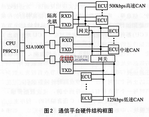
In the design, the main control chip CPU selects 51 series single-chip computers. The CAN communication controller implements a complete CAN protocol and completes communication functions, including information buffering and receiving filtering, so the CAN controller uses Philips' SJA1000. PCA82C250 is used as the transceiver of the CAN bus. PCA82C250 is the interface between the CAN protocol controller and the physical bus. It has anti-transient, anti-RF and anti-electromagnetic interference performance in the operating environment. The internal current limiting circuit has a circuit short circuit. The function of transmitting the output stage for protection. The transmission medium uses shielded electricity charges, and an optocoupler circuit is added between the measurement and control node and the medium to improve the anti-interference ability of the bus interface. Figure 2 is the hardware block diagram of the communication platform, and Figure 3 is the connection interface between the controller and the transceiver.
To further improve the reliability of the system, the redundant design of the system needs to be considered. Due to the harsh car environment and many interference factors, two capacitors were connected in parallel between the CAN_H and CAN_L signal lines and the ground line to filter out noise and make the signal transmission stable. Two sets of double-shielded electricity charges can be set to transmit information simultaneously on the two sets of media. The receiver uses only one medium to switch the bus at the critical point of the connection between the redundant and non-redundant segments.
2.3 Software design
Simply put, the function of this communication platform is to enable each node (ECU) to communicate with each other through the CAN bus, send and receive commands, information, etc., and achieve data sharing, thereby improving their respective control performance and operating efficiency. Each node (ECU) of the CAN data bus on the car has its own address and name. The ECU address indicates the destination of the data transfer, and its name identifies the basic function of the ECN. The node continuously monitors various data sent on the bus. When the received data address value matches its own address, the node obtains the token. In the communication protocol, the only node that has obtained the token has the right to send data to prevent two or more nodes from transmitting data at the same time and causing confusion. At the same time, each node has the opportunity to get a token and complete the data transmission.
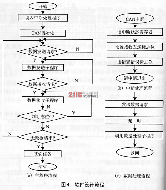
This software design is based on Keil C language. The program is mainly composed of the main module, interrupt processing module and data communication module, as shown in Figure 4.
Figure 4
The main module completes the hardware initialization, register configuration, SJA1000 initialization, etc .; the interrupt processing module includes data interrupt sending, receiving, error handling, and alarm processing; the data communication module completes the data request, sending, and receiving.
When a node A sends a data request message (remote frame) and requests a message from another node B (response frame), after receiving the request, node B discriminates and sends data (response frame). Since the data request has no data field, the relative data frame length is much smaller. After analysis and verification, it is the same as the data received by Node B, and the request data program is verified.
Conclusion
In the design of modern automobiles, the CAN bus has become a trend to build an automobile network; while the automobile network is directly connected to each ECU inside the automobile and is responsible for command transmission, data transmission and sharing, its reliability, stability and integration The performance of the car is closely related. The design and development of this paper is based on the simulation platform built under the experimental conditions, and the communication between the nodes is carried out through the equivalent CAN communication nodes. Tests show that its running performance is stable and reliable, but the practical use still needs further research and improvement, and the program's communication processing ability, error correction and fault tolerance capacity need to be further improved
High Torque 2kw 4kw 5kw Bldc Motors
Bldc Motor High Torque,High Torque 2Kw Bldc Motors,High Torque 5Kw Bldc Motors,High Torque 4Kw Bldc Motors
Jinan Keya Electron Science And Technology Co., Ltd. , https://www.keyaservo.com