1 Introduction
This article refers to the address: http://
With the advancement of technology and the reduction of the cost of electronic components, mobile phones have become an indispensable communication tool in our daily lives. At the same time, cars are approaching our lives and showing a trend of civilians. When people travel long distances or on business trips, if the mobile phone battery is exhausted, it will have a great impact on people's normal working life. Now some car chargers have appeared in some cars, but because there are big differences in the charging interface of different brands of mobile phones, if you want to complete charging in the car, you must carry a charger that matches your mobile phone, not very Convenience. Moreover, due to the limited power supply of the vehicle, it is impossible to simultaneously charge multiple mobile phones. According to the above situation, this paper puts forward the idea of ​​car wireless charger, introduces electromagnetic induction technology into the field of mobile phone charging, realizes the contactless charging of mobile phone through electric-magnetic, magnetic-electrical conversion, and its core technology is similar to the coreless of transformer. Processing.
2 wireless charging ideas
2.1 Overall plan diagram
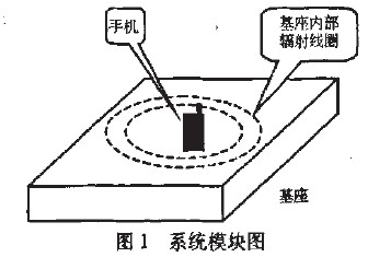
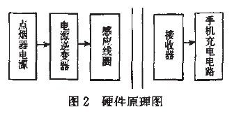
This paper proposes a new car-based solution for mobile phone charging. The block diagram and system hardware diagram are shown in Figure 1 and Figure 2, respectively.
2.2 Hardware components
The car cigarette lighter provides a 12V Dc-550 rrA power supply, which is inverted to the mains by the inverter, and the base of the built-in induction coil is connected to the output of the inverter. Since the square spiral is connected to the connecting portion of the adjacent side, there is a sudden change in current. Therefore, the built-in induction coil uses a circular spiral coil with a radius of 5 cm.
The receiving end of the mobile phone is composed of a receiver module and a charging circuit of the original mobile phone. The receiving induction coil, rectification, and filtering circuit are integrated into a sufficiently small module through PCB technology, and are built in the mobile phone battery, and the output of the receiving module is 5V DC-1A. Provides power to the phone battery to complete the wireless charging function.
3 wireless charging working principle and its parameters
3.1 Working principle
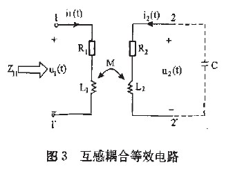
Wireless charging is not directly related to the current of the charger and the receiver. The coil current and voltage are generated by magnetic coupling. The essence is a pair of mutual inductance coupling coils. There is no magnet in the coil. The equivalent circuit diagram is shown in Figure 3. Show:
3.2 induced electromotive force
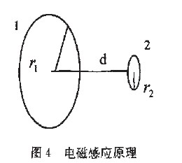
As shown in FIG. 4, the coil 1 and the coil 2 are respectively located in the susceptor and the handset receiving module, and the magnetic induction intensity at the coil ç½” 2 (the number of turns) is assumed to be given to the coil 1 (the number of turns is "." Can be approximated as:

Therefore, it is only necessary to adjust the turns ratio of the two coils to perform the voltage transformation while wirelessly transmitting, and obtain the required charging voltage of the mobile phone.
3.3 Rectification filter
Since the induction coil in the receiver module senses AC power, in order to meet the requirements of the mobile phone charger, it is necessary to add a rectification and filtering circuit to the receiver module.
4 Conclusion
In this paper, the wireless sensor technology is used to study the wirelessization of mobile phone chargers. This allows the charger to charge the battery without direct current contact. And it can provide charging service for many mobile phones in the car at the same time, which is convenient and economical. If it is used in a humid environment such as a bathroom, its safety performance is even more revealing. Therefore, wireless chargers will have extensive research and practical value.
UFO POWER understands that the operation stability is highly required for telecommunication base station. If the base station stops operating abruptly, there would result in various inconvenience to our life in such Internet era, especially for remote connection. Therefore, UFO POWER has designed this 48V 100Ah LiFePO4 Battery which is an ideal selection for telecom base station.
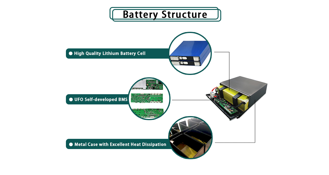
Protection of Rack Mount LiFePO4 Battery for Telecom Towers
â— Over charge/ discharge Protection
â— Over current Protection
â— Over voltage Protection
â— Over temperature Protection
â— Short Circuit Protection
48V 100Ah Lifepo4 Battery,High Rate Discharge Battery,Lithium Battery Discharge Voltage,48V Telecom Battery
ShenZhen UFO Power Technology Co., Ltd. , https://www.ufobattery.com