This article mainly elaborates on the model airplane steering engine. Firstly, it introduces the working principle of the model airplane steering engine. Secondly, it introduces the assembly and testing of the model airplane steering engine. Finally, it analyzes the factors affecting the performance of the model airplane servos. .
First, the mode of operation of the model servoThe model servo is mainly composed of a position detector, a control circuit board, a DC Coreless motor, a reduction gear set and a rudder plate. Its composition principle is shown in Figure 1.

The control circuit board is the heart of the aircraft model servo. It is responsible for receiving and sending signals and controlling the operation of the entire steering gear. The hollow cup motor (hollow cup armature DC permanent magnet servo motor) is made of thin copper wire wound into a very thin hollow cylinder to form a very lightweight coreless hollow rotor, and then the permanent magnet is placed inside the cylinder. Its weight and volume are 1/3-1/2 less than those of ordinary iron core motors. The model servo gears may be plastic gears or metal gears, wherein the metal gears do not collapse due to excessive load. The position detector usually uses a coaxial potentiometer. The rudder is generally mounted on the output shaft of the model servo, and is a component that connects the model servo and the model airplane's connecting rod. It can transmit the power from the servo's servo output shaft to the airplane model.
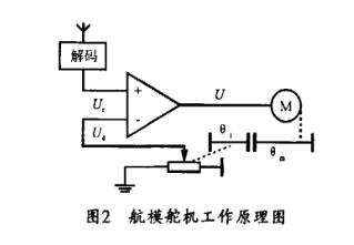
The operating principle of the model servo is shown in Figure 2. In the figure, when the receiver antenna receives the PWM control signal, it is demodulated through the receiving channel into the human signal decoding circuit to obtain a DC bias voltage U. At the same time, the position feedback potentiometer connected to the servo output shaft is also The other position voltage U is fed back to the control circuit. The control circuit compares U with Uj, and sends the resulting electrical difference to the motor drive circuit to drive the hollow cup motor until the voltage difference becomes zero and the hollow cup motor stops rotating. At this point the positional deviation tends to zero and the rudder plate reaches the desired position.
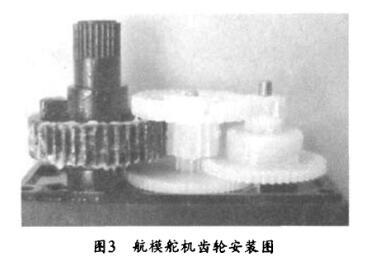
The assembling procedure of the model servo is to install the motor gear on the motor shaft first, and ensure that the motor gear and the upper end surface of the motor leave a slight gap, and then the motor and the potentiometer are loaded on the middle shell, and the circuit board is placed on the middle shell. , Make the potentiometer and the welding foot of the electric motor insert the corresponding hole in the circuit board, and weld it on the circuit board, then install the gear according to the order, Fig. 3 shows its installation figure. After installation, use gear oil, and pay attention to the good meshing between the teeth. The shaft should be vertical in the shell and the gear oil should be even. Finally, put the upper shell on the middle shell and press it tightly. Then adjust the position of the three wires and add the bottom shell to make the screws.
The test items of the model servo include angle (%), torque (Nm), noise (dBA), speed (s/60%), dimensions (mm), test voltage (V) and weight (kg). The unit of speed is sec/60^, which indicates the time required for the position detector of the model servo to turn 609.
1, angle test
The model servo control signal is a pulse width modulation (PWM) signal with a period of 20 ms. The pulse width of the input signal is 0.5-2.5 ms, and the corresponding rudder plate position is 0*~180*. Wu changes linearly. Figure 4 shows the relationship between the servo output angle and the pulse width of the input signal. Because the model servo has correspondence and maintainability, when it is provided with a certain pulse width, the output shaft will remain at a corresponding angle.
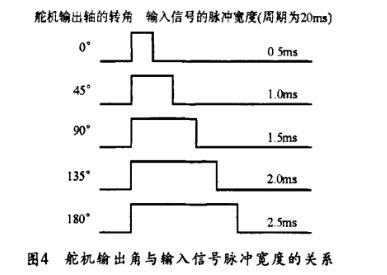
The maximum output angle is the angle (approximately 180) that the model servo steered when a pulse of 0.5-2.5 ms is input. When the pulse width is 0.5 ms, the pointer is aligned with the zero value of the start value. When the model servo enters a 1.5ms pulse, the output angle is 90*.
2, torque test
The torsion test is to use a special torque test fixture and a servo controller to control the model servo under a certain power supply voltage, that is, to test the maximum torque that can be sustained without skidding or chipping.
3, noise test
When the ambient noise is less than 35 dBA, the model servo is connected to the power cord at a specific supply voltage, placed in the noise box and separated from the noise meter in the noise box by 100 mm. Then use the servo controller to control the model servo and record the peak value of the test data.
4, speed test
The aircraft model servo is scheduled on the speed tester, and the tester is placed in a dark box, and the rudder with pointer is fixed on the output shaft. Then, under the specified power voltage, the servo controller controls the model rudder. Machine, the pointer from one corner of the corner to another limit, observe the tester display speed, and record the maximum value.
IV. Analysis of factors affecting the performance of rudder actuatorsFrom the composition of the model servo, the main factors influencing its characteristics are the assembly of the control circuit board, position detector, hollow cup motor and gear set, and their matching has a decisive influence on the overall performance.
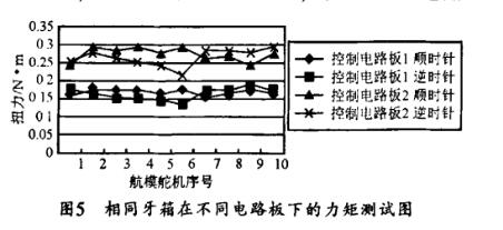
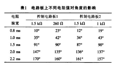
The control circuit board is a key part of the entire model servo, and its influence on the characteristics is obvious. The performance of the model servo should be ensured that under the rated load, the control loop should have less overshoot (the steady-state error is less than 5%). Figure 5 shows the torque test results of two different models of circuit boards with 10 different model servos under the same conditions. As can be seen from FIG. 5, the torque of the control circuit board 1 is smaller than the torque of the control circuit board 2, which shows that the overall performance of the circuit board 2 is better than the overall performance of the circuit board 1. The control circuit board not only affects the torque, but also affects other characteristics. Table 1 shows the influence of different resistance values ​​on the circuit board to the angle. In fact, when the same resistor with a resistance of 1.5kΩ is changed to a different resistance value of 2600 and 1kΩ on the circuit board, the corresponding angle pulse width value will change accordingly, indicating that the change of the circuit board will affect the model rudder. The angle of the machine has a certain influence.
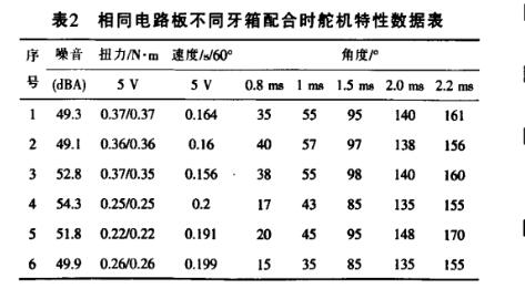
The influence of various parts of the tooth box (including the position detector, hollow cup motor and gear set) on the performance of the model servo is also obvious. The hollow cup motor has a certain influence on its torque, speed and noise. The hollow cup motor will cause some interference to the current input to the circuit board. The degree of interference depends on the quality of the hollow cup motor. The position detector will affect the maximum angle that the model servo can reach. The sensitivity of the model servo is determined by the torsional torque of the position detector. The life of the position detector will inevitably affect the life of the model servo. The gear ratio will affect the outgoing speed and torque of the model servo. The center distance of the gear, the precision of the parts, and the choice of materials have a great influence on their life and noise. The interaction of the position detector, the hollow cup motor and the gear train assembly also has an impact on the characteristics of the model servo. Table 2 lists the test results of the same circuit board with the same model but different tooth box. Among them, the steering gears 1, 2, and 3 are three different tooth boxes of the same model of a manufacturer. The servos 4, 5, and 6 are Another manufacturer of the same model has three different toothed boxes. The six toothed boxes are all equipped with the same control circuit board. The data shows that the performance gap of the toothed boxes of the same manufacturer is not large. The different manufacturers of tooth box on the performance of the steering gear is more obvious. After describing the combination of components of the same model, the overall performance of the servo is slightly different. After the combination of different types of components, the overall characteristics of the servo vary greatly.
The difference in the way of operation during assembly directly leads to different characteristics of the model servo. If the gears are not fully meshed during assembly or the shafts are mounted, the torque may not meet the requirements, and the teeth will be easily hit and a loud noise will occur. If there is no teeth or the bottom cap is not installed, there will be noise and short life.
Comprehensive testing of the model servos and comprehensive evaluation of various performance indicators are important steps to ensure their quality. If the test does not operate in violation of the test standard, then when the part is installed on the finished machine, it is likely to directly cause its performance to decline or become waste.
The voltage will also directly affect the performance of the model servo. Generally, the torque at the 5.0 V power supply voltage is smaller than the torque at the 6.0 V power supply voltage, while the speed at the 5.0 V power supply voltage is greater than the speed at the 6.0 V power supply voltage. In fact, fast, high-torque servos, in addition to requiring a higher power supply voltage, must also be matched with high-quality hollow cup motors, gear sets, control circuit boards, and responsive position detection controllers. High quality, high capacity power battery.
V. ConclusionThe performance of control circuit boards, position detectors, hollow cup motors and gear sets is a major factor affecting the overall performance of the model servo. In order to obtain a well-performing servo, in addition to ensuring the reasonable design and excellent characteristics of each component, it is also necessary to strictly control the assembly process to ensure the matching of various components, so as to ensure the normal stability of the servo performance.
Semiconductor Disc Devices(Capsule Type)
Semiconductor Disc Devices(Capsule Type) is the abbreviation of thyristor, also known as silicon controlled rectifier, formerly referred to as thyristor; thyristor is PNPN four-layer semiconductor structure, it has three poles: anode, cathode and control pole; thyristor has silicon rectifier The characteristics of the parts can work under high voltage and high current conditions, and their working processes can be controlled and widely used in electronic circuits such as controlled rectifiers, AC voltage regulators, contactless electronic switches, inverters, and inverters.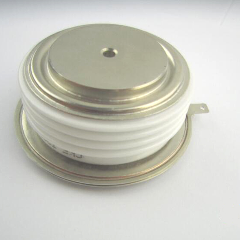
Semiconductor Disc Devices,Inverter Thyristor,Phase Control Thyristor,Capsule Type Semiconductor Disc Devices
YANGZHOU POSITIONING TECH CO., LTD. , https://www.pst-thyristor.com