1 Introduction
The development and application of single-chip microcomputer has penetrated into all aspects of our life. One of the applications is to mass-burn the chips with smaller memory, and there is a high-speed programmer with stable performance to meet the goal of large-scale chip burning by major manufacturers. At present, the most widely used programmer on the market is based on the 89C51, but its function is too single to meet the growing market demand. This paper proposes a programmer that uses the MSP430F149 microcontroller as the CPU control core. Compared with the 51 MCU programmer, the MSP430 MCU programmer adds an I2C memory module, which can be used to burn the chip without using a computer, making the burning process more convenient and faster.
2. System design
The MSP430-based MCU programmer is based on MSP430F149 and is mainly composed of keyboard, display, serial port, programming, level shifting, power supply and storage module. The system structure block diagram is shown in Figure 1.
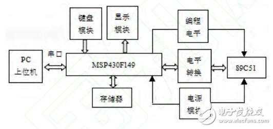
Figure 1 system block diagram
3. Programmer hardware circuit design
3.1, CPU module
The programmer core module selects the ultra-low power MSP430F149 series MCU [1]. Figure 2 is a schematic diagram of the minimum system of the MSP430F149. Y1, Y2 are crystal oscillator modules, RST is connected to reset module, P1 is data transmission port, P3.0~P3.4 is high 4-bit address output, P4 is low 8-bit address output, P5.3, P5.4 and keyboard Connection, P2, P5.0~P5.2 are connected to the liquid crystal display, and P3.6 and P3.7 are connected to the memory.
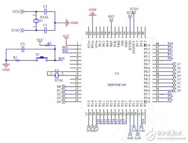
Figure 2 MSP430F149 minimum system schematic
3.2, serial port module
The MSP430F149 provides a signal level that is inconsistent with the operating level of the host computer, so level shifting is performed through the MAX232. The MAX232 chip is an interface circuit designed according to the RS-232 standard serial port and is powered by a single +5V power supply. The MAX232 communicates with the MSP430F149 and the host computer.
3.3, storage module
As shown in Figure 3, the I2C memory module based on the MSP430 programmer is an EEPROM memory, and the AT24C16 chip with 8 KB of memory is selected. A data line SDA and a clock line SCL are connected between the MSP430F149 and the AT24C16. Store the program that will be programmed to 51 MCU to meet offline requirements.
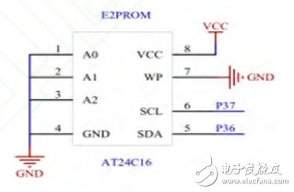
Figure 3 storage module connection diagram
3.4, keyboard and display module
The keyboard module uses PS2 keyboard, which is widely used because it has universal reliability and low connection (only 2 signal lines are used). In the programming, the function selection function is mainly used, and FIG. 4 is a connection diagram of the keyboard module.

Figure 4 keyboard module circuit schematic
The display module selects 1602 liquid crystal display, which displays the parameters related to the programmed chip, such as chip type, programming voltage and read, write, erase and so on. Figure 5 is a diagram showing the connection of the module. The MSP430F149 displays the current status and data of the programmer according to the keyboard control commands.
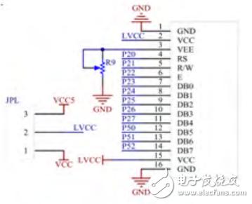
Figure 5 shows the schematic of the module circuit
3.5, power module
The power supply provides a 3.3V operating voltage to the MSP430F149 chip and a 12V programming voltage to the programmed 51 chip. As shown in Figure 6, the +5V power supply is converted to a voltage of 3.3V by the ASM1117-3.3V to provide a voltage of 3.3V to the MSP430F149 microcontroller. The +5V power supply is directly input to the 51 chip and generates a 12V programming voltage.
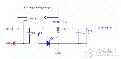
Figure 6 Power module connection diagram
3.6, programming module
In the programming module, 89C51 is the programmed chip, P0.0~P0.7 is the data input, P1.0~P1.7 is the low 8-bit address input, P2.0~P2.3 ​​is the high 4-bit address input and P3 .6, P3.7 as the function control port [2]. As shown in Figure 7, the 51-chip peripheral link 4 74LVC8T245 realizes 3.3V to 5V voltage conversion. DIR controls the signal transmission direction. When the pin is high, the data bus transmission direction is from A1 to A8 to B1 to B8. When it is low, it is reversed. DIR is active low for the three 74LVC8T245s that are connected to the address and control.

Figure 7 89C51 microcontroller programming connection diagram
4. Programmer function and software design
The MSP430 based microcontroller programmer has the functions of read, write, verify and erase. These functions can be operated by command mode in the online state, or by keyboard control in the offline state, and programming data and command transmission are realized by communication between the upper and lower computers.
As shown in Figure 8, the programmer enters the interrupt state and waits to receive data. Once the data is received, it is judged whether it is a "command". If so, it is judged whether it is a "check", "erase", "read" or "write" command. First, the programmer performs the corresponding operation. Otherwise, it returns to the serial port interrupt receiving state and waits for the data to arrive. If it is not a "command", it is judged whether it is "data". If it is, the data is stored in the E2PROM, otherwise the programmer returns to the interrupt receiving state.
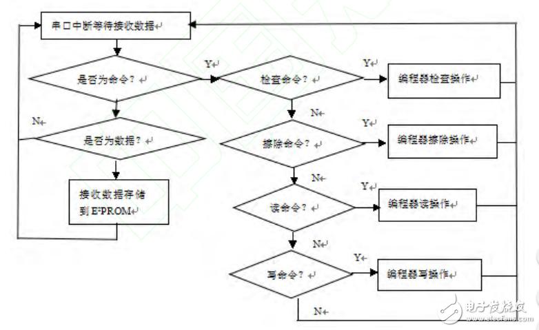
Figure 8 Flow chart of serial communication and online programming program of lower computer
As shown in Figure 9, the programmer reads the keyboard input command. If you input "Check#", check the 51 MCU Flash. If it is FFH, the LCD will display "OK", and also display the MCU ID, programming voltage and other information, otherwise the display will not be erased. In addition to the unit address; if the input "Erase#" programmer will erase the contents of the 51 MCU Flash and display "Complete" on the LCD; if the input "Read#" programmer will read the contents of the 51 MCU Flash into the RAM and on the LCD Displayed; if the input "Write#" programmer will write the E2PROM memory content to 51 MCU Flash, and display "Complete" on the LCD; if the input is "Verify#", the programmer will check the contents written in Flash. Whether it is consistent with the content of E2PROM, if "OK" is displayed on the LCD, otherwise the error FLASH unit address is displayed; if the "Auto#" programmer is input, the erase, check, write and verify operations are sequentially performed and the waiting keyboard input command is returned.
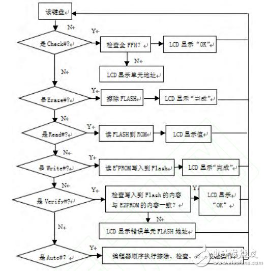
Figure 9 bottom machine offline programming software flow chart
The functions of reading, writing, erasing, etc. of the programmer are implemented by the following main functions.
#include"common.h"
voidInit_Read(void){...}//Read data initialization
charReadByte(intaddr){...}//read data
voidEraseByte(intaddr){...}//erase data
voidCheckByte(intaddr){...}//Check if the data is empty
voidVerifyByte(intaddr, indaddr1){...}//Check data
voidInit_Write(void){...}//Write data initialization
voidWriteByte(intaddr,chardat){...}//write data
charReadID(intaddr){. . . }//Read chip ID
Voidmain(void)
{charUART1_RX_Temp[10];
nRev_UART1=0;
nSend_TX1=0;
write_Flag=0;
dat_Flag=0;
Dat_buf=0;
nDAT_BUF_Valid=0;
_DINT();//Close interrupt
Init_CLK (); / / initialization clock
Con_Port_Init();//Initialize port
CT_OE_Enable();
Init_UART1 (); / / initialize the serial port 1
_EINT();//Open interrupt
ResetSM();
For(;;)// enter the processing loop
{...//various programming commands; read keyboard and LCD display, etc.
}
5 Conclusion
Through the research of the design principle and ideas of the programmer based on MSP430 microcontroller, the programming operation of the 89C51 series chip is realized. In actual test, the programmer can perform chip programming work quickly and independently, greatly improving the speed of the programming chip, and making it have higher working efficiency and better stability.
Any skin. Double sunscreen spray, can effectively prevent the sun's UVA UVB rays infringement, skin sensitive to sunlight especially suitable. Hypoallergenic, preservative-free, clinically tested by dermatologists; fragrance-free, non-alcoholic, non-acne formula, waterproof formula.
Companies registered capital of 35 million yuan, the end of 2014 the total assets of 48.69 million yuan, including fixed assets of 37.52 million yuan. The company's existing cooperation Orange cultivation base 7043.5 acres, the company production base is located in Jiangxi County Tech Industrial Park Chu Tan industrial area, covers an area of 120 acres, it has built a standard plant 9,000 square meters, Nissan 6000 kg Orange enzymes and other liquid enzyme products. Enzyme, known as enzyme, refers to a polymer substance having biocatalytic functionality. In the catalytic reaction system an enzyme, the reactant molecules are known as substrates, enzyme substrates by catalytic conversion to another molecule. Almost all cellular activity of enzymes involved in the process are required to improve efficiency. Similar to other non-biological catalysts, enzymes chemical reactions by lowering the activation energy to accelerate the rate of the reaction, most of the enzyme catalyzed reaction rate can be increased a million times; in fact, the enzyme is to provide an activation energy needs than another low way, so that more particles to have less than the activation energy of the reaction kinetic energy, thus speeding up the reaction rate. Enzyme as a catalyst, in itself is not consumed during the reaction, it does not affect the chemical equilibrium reactions. Positive enzyme catalysis, but also a negative catalytic effect, not only to accelerate the reaction rate, but also to reduce the reaction rate. And other non-living catalysts is different, having a high degree of specificity of enzyme, only a catalytic reaction or produce a particular specific configuration.


Skin Care Enzyme Spray ,Orange Fragrance Enzyme Spray,Dual Sunscreen Enzyme Spray,Fragrance Free Enzyme Spray
guangdong ganzhou ningbo , https://www.tlqcjs.com