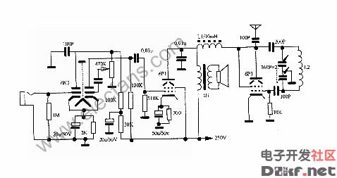
Four-lamp tube transmitter circuit
The machine has simple lines, stable operation and good performance. The required components can be purchased by the market. In 1992, the self-made teaching aids exhibition in Suihua area was well received by the teachers.
This machine can be used as a classroom demonstration, or it can broadcast records or close-range communication. It has less distortion and better frequency response.
The machine includes audio amplification and oscillation and two parts. The audio amplification consists of voltage discharge and power amplification, which are respectively performed by the double triode 6N2 and the beam quadrupole 6P1, and the oscillation part is also performed by 6P1.
The audio signal is input from the gate of the tube G1 (6N2). After two amplifications, the signal strength sent to the power amplifier stage G2 (6P1) can be controlled by the 470K potentiometer. The amplified audio signal and the high-frequency oscillation signal oscillate. The screen of the class tube G3 (6P1) is mixed so that the high frequency oscillating current carrying the audio signal to be transmitted is transmitted through the antenna. If you do not need **, you can replace the field sounder Y and connect a 3.5 ohm resistor to the B1 secondary.
The power supply is powered by an AC five-lamp radio, which is rectified by the tube 6Z4 and filtered to obtain a stable DC.
The transformer B1 used in this machine is an output transformer with a 6P1 tube. The secondary impedance is 3.5 ohms, L1 is a choke coil with an inductance of 10 mH, and the L2 can be a medium-wave oscillating coil of a general super-heterodyne radio.
The output power of this machine is 2~3W
Transmission frequency 550 kHz ~ 1600 kHz
Power consumption 40W
Launch distance of 1 km

Grid Fan ,Grid Ceiling Fan,Off Grid Ceiling Fan,Off Grid Fan
Hangzhou Jinjiu Electric Appliance Co Ltd. , https://www.jinjiufanmotor.com