Abstract: The functional safety of automobiles is one of the key points in the development of current automotive technology, and it is also a weapon for car manufacturers to compete. The realization of safety is related to communication. Now more than 90% of the vehicles use CAN bus to realize communication for control. It has been found that the CAN bus has high error frame miss detection and long equivalent offline and true offline mechanism hazard. This paper further analyzes the occurrence probability and consequences of these two hidden dangers. The missed frame may be the most 33 times or 1/33 of the data, the failure probability caused by equivalent offline can reach 16.8/h when the bit error rate is 10-5 (bus utilization 40%, rate 500 kbps, average frame length 100 bits). If the error frame miss detection occurs first, the application receives the wrong frame, and the offline occurs again, blocking the correction of the correct frame, and the application will work in the wrong state for a long time, which is very dangerous.
Key words: CAN; error frame miss detection; offline; functional safety
Introduction The international standard for functional safety of ISO26262 road vehicles has been adopted. It is self-interested for car companies to implement this standard, because it can reduce the compensation losses after the accident, and it is also one of the means of competition for customers. Therefore, it is very necessary to review existing practices. The reference states that ISO 26262 emphasizes the cultural philosophy of safe management and safety. Security is no longer just an after-the-fact risk assessment. He also recommends implementing ISO262 62 with the system theoretic processhazard analysis method. In this method, the process of information transmission between people, organizations, machines, etc., and their risks must be evaluated. As the information transmission between the vehicle control devices, the current vehicle is mainly the CAN bus, and the risks caused by the loss of the CAN bus frame, the error of the wrong frame, the error of the delivery sequence, and the exceeding the time limit should be quantitatively analyzed.
In this article, I have published several articles on the hidden dangers of CAN bus. In short, there are mainly two fatal hidden dangers: very large missed frame miss rate, which is several orders of magnitude larger than Bosch claims; Mismatch, equivalent offline caused by continuous errors, the possible duration is very long. These two kinds of errors will affect the security alone. If the risk is even connected, the application will receive the wrong raw data when the first fault occurs, and then the second fault will block the data refresh. The application error continues for a period of time, causing a system security incident.
1 Value Mistakes Caused by Missing Frame Missing Check Figure 1 shows two examples of bit error detection and bit error detection. The specific construction method can be found in the reference. They all satisfy the error Ec=U·G, where G is the CRC generator polynomial G=(110o, 0101, 1001, 1001) of the CAN bus. In the figure, Ec=U·G=(1000,0010,0001, 1100, 1110, 1001). Since Ec is a multiple of G, the CRC check does not go wrong.
This article refers to the address: http://

When constructing an example of mis-frame miss detection, the role of the first one is to ensure that the fill rule occurs after the sixth bit. This 1 can be either the code that occurs in the DLC or the filled-in 1 in the data field. So its value can be ignored as the value of Tx and Rx. In this case, if the first dislocation occurs at the 2nd bit of Tx, the received Rx value will be 33 times Tx, or 1/33. If the first dislocation occurs in the next few digits, the Rx value will also change many times than Tx.
2 Equivalent offline occurrence probability Equivalent offline has three conditions: 1 node is already in the passive passive status; 2 the node has a local error; 3 due to other errors encountered in the negative error frame delimiter The node suspends the sending of the pending frame and causes a continuous error. What is to be considered is the probability of an error due to an error and the probability of being at the peak load of the bus.
Negative error frame specification: When reading six consecutive identical bits when transmitting consecutive hidden bits, it is regarded as the error flag is sent, and then the hidden bit is started. When the hidden bit is read back, it starts as the negative error frame delimiter. It must be started after the start. For 7 consecutive hidden bits, if there is a bit in the inside, as a new error, the node should retransmit the negative error frame.
For the passive error sending node, there are two types of local errors. When the ACK delimiter is in front of the ACK delimiter, the continuous hidden bit of the passive error flag will be checked by the receiving node with the filling rule, and the CRC check finds that there is an error, causing the receiving node to report an error. The six consecutive bits of their active error frame determine the synchronization of the end time of the passive error frame error flag of the transmitting node, and no error occurs in the delimiter.
When there is a local error between the ACK and the delimiter to the 3rd bit of EOF, the 6 hidden bits of the passive error flag (P.E.Flag) will be considered as the normal end of the transmission frame and the 2-bit service interval by the receiving node (I .M.). The new frame start bit (SOF) sent by other nodes will fall into the passive error frame delimiter (P.E.Del) of the transmitting node, forming a new error, as shown in Figure 2. The new passive error frame of the transmitting node will start at the ACK delimiter of the new frame. Then, as long as there are pending frames to be sent, this error state is repeated. The negative error frame sent by the 4th to 7th EOF sending nodes does not see consecutive 6 identical bits. The sending node has to wait for the ACK delimiter of the new frame sent by another node to start, which is equivalent to A passive error frame starting at the ACK delimiter. It can be seen that the number of positions that generate an equivalent offline error is 9 bits, and the probability is 9·BER.

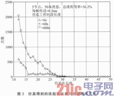
After the transmission node in the passive error state encounters 16 repeated errors, it will enter the true offline state, so it is required to take 16 frames to suspend the opportunity to be sent. This is related to the design of the ECU and is difficult to analyze. We use simulation to obtain. There are generally 6 nodes in the chassis CAN bus system. About 60 messages are transmitted. Each node has an average of 10 messages, assuming a period of 10 ms, 20 ms, 50 ms, There are two each of 100 ms and 1 000 ms, each frame is 97 bits long, and the bus load rate of 6 nodes at 500 kbps is 43.4%. When a node is equivalently offline, there are about 50 messages to send. Under the influence of the clock difference, a peak can be formed. The simulation results of the nodes at relative frequency differences of -0.2, 0.4, 0.6, and 0.8×100 ppm are shown in Fig. 3. The length of the team is counted every 0.2 ms, and the number of occurrences of the captain during the entire simulation time is accumulated.

To facilitate ECU programming, the sample and write CAN bus controllers are completed in one task, so assume that 10 messages are ready within 4 ms. The simulation starts with the worst case: all nodes start writing CAN bus controller tasks at the same time. Under the above frequency difference, the nodes 1 and 2 are 10 ms out of 500 s, which means that the message ready time of the 10 ms period of the two nodes coincides again. The combination of other nodes and node 1 is 250 s, 166 s, 125. s. Since the longer period message has less impact on the suspended captain, the simulation period is shorter. Calculated with a result of 600 s, there are 3 590 times of suspending lengths of 16 or more, accounting for 1.2×10⁻³ transmitted within 600 s. It is important to note that the distribution of the captains is not uniform, so the chances of being offline and turning to true offline are not evenly distributed. From the results of the above simulation of 60 s, 600 s, the case of suspending the length of 16 or more is 3 590 times, and if it is encountered in the worst case 60 s, it is 1.2 × 10⁻². If there are 1 005 times in the worst case 6 s with a suspension length of 16 or more, the chance is 3.3×10⁻².
The length of the team's length 18 is 17 more than the team length. The explanation is as follows: Although each 18 teams will go through 17 teams and drop, but in 18 teams, they may grow to 19 teams or longer. When they retreat It has to go through 18 teams. At some point, since there are more than two messages at the same time, the team length is directly jumped from 18 to 18, so that the 18 teams appear more than 17 teams.
Therefore, the probability that the passive error reporting node is equivalent to offline and enters the true offline is P=BER×9×1.2×10-3, where BER is the error rate. This is an optimistic estimate.
For a passive error receiving node, a local error occurring in any bit in the frame may result in a similar situation, that is, a situation in which the other node hangs the pending frame in the negative error frame delimiter, causing a re-error. Assuming a frame length of 135 bits, the probability of its equivalent off-line is P = BER x 1 35 x 1.2 x 10-3.
3 Offline time The node that is equivalent to offline can no longer be sent, so the frames whose source is the node should be deducted. The analysis method at this time can refer to the traditional scheduling analysis method of the CAN bus, and the worst case is the delivery time of the lowest priority message. The results of this analysis are related to the specific configuration of the application and are different for each node.
Assume that the pending message has 4 bytes of data, 11-bit ID, 8 bits of average padding, and 3 bits of service interval. The equivalent offline caused by 16 frames is 16×(84+3)=1. 392 bits, the time for true offline is 128 frames, and the worst case is 10 bits of idle time between frames. So really offline there will be 128 x (84 + 3 + 10) = 12 416 bits. Adding the two together, the negative error sending node will have a total of 13,808 bits of unserviceable time. At 500 kbps, this is equivalent to 27.6 ms. If a 29-bit ID is used, the padding bit is also increased, and the frame length is changed to 105 bits. At this time, the time for the passive error sending node to fail to service will be 34.5 ms. Some cars use a 250 kbps rate, which will have a time of 69 ms unserviceable.
4 2 hidden dangers in the application of the hidden dangers actually appear as a system failure.
4.1 The effect of missed frame miss detection In the case of a single receiving node, the information range of the error frame transmission varies greatly. Some application algorithms add an absolute value limiter, or a speed limiter. Reduce the danger of this failure. But these measures are sometimes not feasible, or at the expense of reducing the dynamic performance of the system, which is clearly undesirable for the application design department.
In the case of multiple receiving nodes, this failure causes data integrity problems. For example, in the throttle, clutch and brake system, the opening of the throttle has different interpretations, and the system is difficult to coordinate.
In a redundant system, if there is no voting mechanism, it is possible to receive the wrong data, and it is necessary to add software and time resources to solve the problem.
4.2 Impact of offline As mentioned above, the time for the passive error sending node to fail to service after the error is up to 34.5 ms is unacceptable in some applications, such as the Electronic Stability Control (ESP), Bosch ESP8 requirements. The signal update period is a minimum of 20 ms. The time when the passive error receiving node fails to serve is short, but the probability of its occurrence is much greater than the probability that the passive sending node cannot service after the error (15 times), and its impact has not been fully studied.
When the vehicle is running at 100 km/h, a delay of 34.5 ms to start braking means that it has moved 0.94 m, which is unacceptable to the driver. In 2010, Toyota's Prius brake energy recovery software had a 0.06 s delay, resulting in a brake distance of 0.6 m and a recall.
4.3 Two faults occurred one after another, the application received a wrong data, and then the second fault occurred. It is very dangerous to not correct the first error. For example, when the inward motion is moving, the steering angle is 5°, but the frame sent by the electric power steering ECU to the ESP-ECU is misread at 30°, and the ESP helps achieve 30° steering, such as ESP-ECU or electric power steering ECU. Offline failure, the 30° error command is still retained within 34.5 ms, and it will rush to the isolation zone or the other lane.
The probability is analyzed below: assuming that the bus operates at 500 kbps, the bus load rate is 40%, and the average frame length is 100 bits, then 7.2 x 10⁶ frames are sent every hour. The author made a new correction to the reference, and the probability of missed frame miss detection is Pud=1.67×10⁻⁷, which is still several orders of magnitude higher than Bosch's (Pud=4.7×10⁻¹¹), and Tran's The results were similar (Pud = 1.3 × 10⁻⁷).
Considering the channel error probability = 0.001 (which takes into account the uneven distribution of the bit error rate, for example, 1 frame per 1000 frames), the residual rate can be calculated as Pres = 1.67 × 10⁻¹⁰. The failure rate Pfailure1=1.2×10⁻³/h caused by the first failure can be calculated. When ber=0.001, the probability of occurrence of the second fault P2nd=1×10⁻⁵, resulting in a failure rate of Pfailure2=72/h. From this, it is inferred that the failure rate Pfailure1+2=1.1×10⁻³/h when two faults occur one after another.
The CAN bus has been used in safety-critical systems such as Electronic Stability Control (ESP). According to the requirements of ASIL-C, the international standard for functional safety of road vehicles, the failure rate of the system should be less than 10-7/h. This includes many factors that may fail, such as sensor failure, CPU failure, connector failure, power failure, etc., even if the pins are not tightened. The share allocated by the communication system is generally 1%, that is, it is required to reach less than 10-9/h. It can be seen from Table 1 that both the wrong frame miss detection and the offline fault cannot be achieved. Even in ESP, the probability of failure due to two consecutive failures is quite large, and the safety requirement can only be achieved if the bit error rate is less than 10-4. The actual interior environment is very poor. In order to save costs, some automakers have insufficient processing of electromagnetic interference sources, and interference may cause a large error rate. There is also the influence of the environment outside the car, and the interference near high-voltage lines, high-power stations, radar stations, etc. is large. This can cause the bit error rate to be greater than 10-4, which will invalidate the system.
5 Software patch solution implementation difficulties In the reference, it is proposed to add an additional CRC test to improve the error frame miss detection, which is difficult to implement for existing applications. It takes up the data field and is generated and verified by the application software. It takes a certain amount of time. After the error is detected, another frame is sent to notify other nodes and resend is required. All nodes have timers to achieve consistency, greatly delaying the entire receiving process. The time of error retransmission is also greater than the time of the original CAN bus, which destroys the result of the original scheduling analysis, so it needs to be re-authenticated.
Existing applications that already use 8-byte data need to be split into 2 frames. Need to increase the identifier, this will increase or modify the filter settings at the receiving node, but also increase the merge mechanism. This has increased the verification of software work and its correctness, especially when it comes to ECUs from different manufacturers.
For the equivalent offline problem, in addition to modifying the length of the negative error frame delimiter, it is also possible to use the method of completely canceling the negative error status: for example, using the commercially available CAN bus chip error counter to achieve an interrupt of 96 hours, the application decides how to modify the working mode. The new mode can be that if the communication has failed, it will enter the derated state, and at the same time reset the communication, and then put it into normal operation after a while. This approach turns the offline time into a constant and lets the application know. It does not reduce the probability of going offline, it just reduces the time it takes to go offline.
The problem with this solution is that the process from derating to derating is not safe (no brakes, the car does not slow down immediately). In addition, frequent switching between normal/derating modes can cause consumer anxiety, loss of trust in vehicle reliability, and is extremely detrimental to the depot.
It can be seen that the software patch solution has very limited improvements to existing vehicles.
The above-mentioned analysis of the CAN bus hidden danger is completely caused by the poor design of the protocol, so the agreement should be changed. Inheriting the advantages of the CAN bus, the physical layer can still be used, the cable does not need to be changed, and even the printed version does not need to be changed, and it may still be appropriate to use a safety-critical occasion.
Antenk latach connector DIN 41651,Those products are used in more or less every known application within computer-, industrial-, telecommunication and specific automotive markets. This product technology allows cost effective connections between printed circuit boards based on removable or permanent connections based on a longterm proofed way of assembly. latch header connectors are available with the traditionally used pitch of 2.54mm and the pitch of 2.00mm,1.27mm.
Antenk Box header/Ejector header Description and Application:
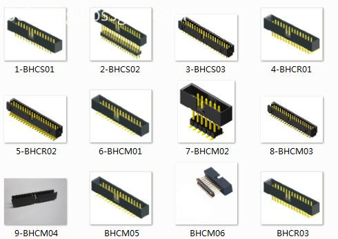
Box header/ ejector header connector, With DIP straight/vertical, SMT,Right angle, 2.54pitch, 2.0pitch, 1.27pitch,
The commonly used Pin ways have 6P,8P,10P,14P,16P,20P, 24P,26P,30P,34P, 40P,50P,64P.
Box header/ ejector header and IDC Flat Cable connectors are two of the most commonly used connectors. Box headers can be found in nearly all electronic equipments.
This is a IDC product which allows cost effective connections between circuit boards based on permanent connection (using transition connector) or removable connection
(Using for IDC flat cable connectors).
Box header

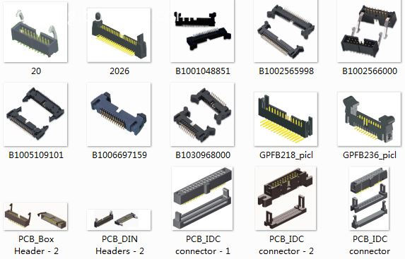
Ejector header

Pcb Header,Latch Header Connectors,Ejector Header,Latch Ejector Connector,Box Header Connector With Latch ,Box Header Lock Type Connector
ShenZhen Antenk Electronics Co,Ltd , https://www.antenk.com