I2C configuration
staTIc void IniTI2C()
{
I2C_InitTypeDef I2C_InitStructure;
GPIO_InitTypeDef GPIO_InitA;
RCC_APB1PeriphClockCmd (RCC_APB1Periph_I2C1, ENABLE); // Enable the clock of I2C1, I2C2
RCC_I2CCLKConfig(RCC_I2C1CLK_SYSCLK);//clock source setting
GPIO_PinAFConfig(GPIOB, GPIO_PinSource8, GPIO_AF_1); //Configure PB8 as the second function pin I2C1_SCL
GPIO_PinAFConfig(GPIOB, GPIO_PinSource9, GPIO_AF_1); //Configure PB9 as the second function pin I2C1_SDA
GPIO_InitA.GPIO_Pin = GPIO_Pin_8 | GPIO_Pin_9;
GPIO_InitA.GPIO_Mode = GPIO_Mode_AF;
GPIO_InitA.GPIO_Speed ​​= GPIO_Speed_50MHz;
GPIO_InitA.GPIO_OType = GPIO_OType_PP;
GPIO_InitA.GPIO_PuPd = GPIO_PuPd_UP;
GPIO_Init(GPIOB, & GPIO_InitA);
I2C_InitStructure.I2C_Mode = I2C_Mode_SMBusHost;
I2C_InitStructure.I2C_AcknowledgedAddress = I2C_AcknowledgedAddress_7bit;
I2C_InitStructure.I2C_AnalogFilter = I2C_AnalogFilter_Enable;
I2C_InitStructure.I2C_DigitalFilter = 0x01;
I2C_InitStructure.I2C_OwnAddress1 = 0x00;
I2C_InitStructure.I2C_Ack = I2C_Ack_Enable;
I2C_InitStructure.I2C_TIming = 0x0090174F;
I2C_Init(I2C1, &I2C_InitStructure);
I2C_Cmd(I2C1, ENABLE);
}
The same configuration program, I2C_TIming meaning please step this blog GY30 that article.
I2C pin is PB8 and PB9 (C8T6 used, f4p6 can use PA)
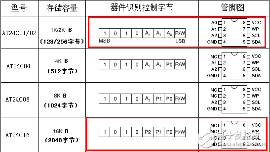
#define AT24C16_Base_Address 0xA0
Void AT24C16_WriteByte(uint8_t Page, uint8_t WordAddress, uint8_t Data);
Uint8_t AT24C16_ReadByte(uint8_t Page,uint8_t WordAddress);
Void AT24C16_PageWrite(uint8_t Page, uint8_t WordAddress, uint8_t Length, uint8_t* Data);
Void AT24C16_SequentialRead(uint8_t Page, uint8_t WordAddress, uint8_t length, uint8_t* p);
Here are the related functions:
Void AT24C16_WriteByte(uint8_t Page, uint8_t WordAddress, uint8_t Data)
{
If(WordAddress > 0x10)
{
Return;
}
WordAddress |= ( Page & 0x0F ) << 4;
While(I2C_GetFlagStatus(I2C1, I2C_FLAG_BUSY) != RESET);//IF BUSY
I2C_TransferHandling(I2C1,AT24C16_Base_Address | ( (Page 0xF0) >> 3),2,I2C_AutoEnd_Mode,I2C_Generate_Start_Write);
While(I2C_GetFlagStatus(I2C1, I2C_FLAG_TXIS) == RESET);//If Write OK
I2C_SendData(I2C1,WordAddress);
While(I2C_GetFlagStatus(I2C1, I2C_FLAG_TXIS) == RESET);//If Write OK
I2C_SendData(I2C1,Data);
While(I2C_GetFlagStatus(I2C1, I2C_FLAG_STOPF) == RESET);
}
Uint8_t AT24C16_ReadByte(uint8_t Page, uint8_t WordAddress)
{
Uint8_t Recev = 0x00;
If(WordAddress > 0x10)
{
Return 0;
}
WordAddress |= ( Page & 0x0F ) << 4;
While(I2C_GetFlagStatus(I2C1, I2C_FLAG_BUSY) != RESET);//IF BUSY
I2C_TransferHandling(I2C1,AT24C16_Base_Address | ( (Page 0xF0) >> 3),1,I2C_SoftEnd_Mode,I2C_Generate_Start_Write);
While(I2C_GetFlagStatus(I2C1, I2C_FLAG_TXIS) == RESET);//If Write OK
I2C_SendData(I2C1,WordAddress);
While(I2C_GetFlagStatus(I2C1, I2C_FLAG_TC) == RESET);
I2C_TransferHandling(I2C1,AT24C16_Base_Address | ( (Page 0xF0) >> 3),1,I2C_AutoEnd_Mode,I2C_Generate_Start_Read);
While(I2C_GetFlagStatus(I2C1, I2C_FLAG_RXNE) == RESET);
Recev = I2C_ReceiveData(I2C1);
While(I2C_GetFlagStatus(I2C1, I2C_FLAG_STOPF) == RESET);
Return Recev;
}
The following is page read, page write:
Void AT24C16_PageWrite(uint8_t Page, uint8_t WordAddress, uint8_t Length, uint8_t* Data)
{
Uint8_t i = 0;
If(WordAddress > 0x10)
{
Return;
}
WordAddress |= ( Page & 0x0F ) << 4;
While(I2C_GetFlagStatus(I2C1, I2C_FLAG_BUSY) != RESET);//IF BUSY
I2C_TransferHandling(I2C1,AT24C16_Base_Address | ( (Page 0xF0) >> 3),Length + 1, I2C_AutoEnd_Mode, I2C_Generate_Start_Write);
While(I2C_GetFlagStatus(I2C1, I2C_FLAG_TXIS) == RESET);//If Write OK
I2C_SendData(I2C1,WordAddress);
For(i = 0;i < Length; i++)
{
While(I2C_GetFlagStatus(I2C1, I2C_FLAG_TXIS) == RESET);//If Write OK
I2C_SendData(I2C1,Data[i]);
}
While(I2C_GetFlagStatus(I2C1, I2C_FLAG_STOPF) == RESET);
}
Void AT24C16_SequentialRead(uint8_t Page, uint8_t WordAddress, uint8_t length, uint8_t* p)
{
Uint8_t i;
If(WordAddress > 0x10)
{
Return;
}
WordAddress |= ( Page & 0x0F ) << 4;
While(I2C_GetFlagStatus(I2C1, I2C_FLAG_BUSY) != RESET);//IF BUSY
I2C_TransferHandling(I2C1,AT24C16_Base_Address | ( (Page 0xF0) >> 3),1,I2C_SoftEnd_Mode,I2C_Generate_Start_Write);
While(I2C_GetFlagStatus(I2C1, I2C_FLAG_TXIS) == RESET);//If Write OK
I2C_SendData(I2C1,WordAddress);
While(I2C_GetFlagStatus(I2C1, I2C_FLAG_TC) == RESET);
I2C_TransferHandling(I2C1,AT24C16_Base_Address|( ( Page & 0xF0 ) >> 3 ),length,I2C_AutoEnd_Mode,I2C_Generate_Start_Read);
For(i = 0;i < length;i++)
{
While(I2C_GetFlagStatus(I2C1, I2C_FLAG_RXNE) == RESET);
p[i] = I2C_ReceiveData(I2C1);
}
While(I2C_GetFlagStatus(I2C1, I2C_FLAG_STOPF) == RESET);
}
Feel nothing to say, GY30 that article basically finished, add a little knowledge point.
I2C_AutoEnd_Mode, as the name implies, automatically adds STOP after the length byte is manipulated.
I2C_SoftEnd_Mode, as the name implies, requires manual addition of STOP after the length byte has been manipulated. ( I2C_GenerateSTOP() )
This mode is one step further than automatic. It requires I2C_GetFlagStatus(I2C1, I2C_FLAG_TC), Translate Completed, whether the transfer is complete, accessing this in automatic mode will get the Reset value, however, in manual mode, you need to access it and generate Stop.
Then... almost? Give an example of the above URL, I think many people will not see ...
So when writing the program to write data to the third byte of page 100 of AT24C16, the steps are as follows:
1) Send start signal;
2) Send the device address 0XA6 (1010 0110, 1010 is a fixed address, 011 is the upper three bits of the page address, 0 indicates a write operation);
3) Send operation address 0X43 (0100 0011, 0100 is the lower four bits of the page address, 0011 is the page address offset, the third byte in page 100,
4) Send the data to be written,
5) Send a termination signal.
I believe that at least you see the address of AT24C16, 0xA0. (Cite Changhong Electronic Network again)

P0P1P2 is the high address of the page address, the word address (WordAddress) sent is the fourth highest address of the page address, and the lower four bits are the word address.
The AT24C16 has 128 pages, 16 bytes per page. So just match.
The write interval is at least 5ms, otherwise the I2C will be stuck with a loop waiting.
the above.
600Mbps Wireless-wifi Repeater
About this item
1. Ideal for boosting existing network to hard-to reach area, delivering fast and stable wireless connection, transfer rate up to 600Mbps
2. Repeater/AP modes for extending wifi or create wifi hotspot, watch video on line, play games, online shopping without interference
3. Activate passion for your life, mobile devices at full signal, wall mounted design flexible to place and 7 steps to finish setup
4. Designed with mobility and portability, little gadget with great value, One-touch wireless security encryption with WPS button
5. Ethernet port allows the Extender to function as a wireless adapter to connect wired devices, Compatible with 802.11n/g/b devices
2 Working Modes:(Select
based on your needs)
Repeater Mode
Plug WiFi Booster into your power
socket, easily expand your existing WiFi coverage to signal dead zones
Access Point Mode
Connect your router signal with
Ethernet Cable, cover a wired network to a wireless access point.
600Mbps Wireless-Wifi Repeater,Wifi Amplifier,Wireless Extender,Wifi Booster For Home
Shenzhen Jinziming Electronic Technology Co.,LTD , https://www.powerchargerusb.com