Lithium-ion batteries are secondary batteries (rechargeable batteries), which rely mainly on Li+ to work in and out of and between two electrodes. With the continuous development of downstream industries such as energy vehicles, the scale of lithium-ion battery production is continuously expanding.
First, the working principle 1, positive structure
LiCoO2 + Conductor + Adhesive (PVDF) + Current Collector (Aluminum Foil)
2, negative structure
Graphite + Conductive + Thickener (CMC) + Binder (SBR) + Current Collector (Copper Foil)
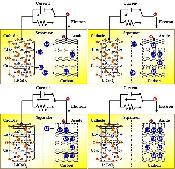
3, working principle
3.1 Charging process
A power source charges the battery. At this time, the electron on the positive electrode runs from the external circuit to the negative electrode. Positive lithium ion Li+ “jumps into†the electrolyte from the positive electrode, and “climbs over†the sinuous hole in the diaphragm. Swim" reaches the negative and combines with the electrons that have long since ran. at this time:
The reaction on the positive electrode is:
 The reaction on the negative electrode is:

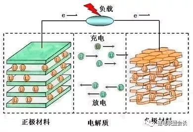
3.2 Battery discharge process
Discharge has a constant current discharge and constant resistance discharge, constant current discharge is actually in the external circuit plus a variable resistance that can change with the voltage change, the essence of the constant resistance discharge is to add a resistor in the battery positive and negative electrodes let the electrons pass. It can be seen that as long as the electrons on the negative electrode cannot run from the negative electrode to the positive electrode, the battery will not be discharged. Both electrons and Li+ act at the same time, but they have the same direction but different paths. When discharging, electrons run from the negative electrode through the electron conductor to the positive electrode, Li+ ions jump from the negative electrode into the electrolyte, and they climb over the diaphragm. The small hole, "swimming" reaches the positive, combined with the electrons that have long since ran.
3.3 Charge and discharge characteristics
The cathode of the cell adopts LiCoO2, LiNiO2, and LiMn2O2. LiCoO2 is a crystalline structure with stable layer structure. However, when the x Li ions are removed from LiCoO2, the structure may change, but whether the change depends on x size.
It was found through research that when x > 0.5, the structure of Li1-xCoO2 was extremely unstable, and the crystalline structure collapsed. The external appearance of Li1-xCoO2 was the overwhelming end of the cell. Therefore, during the use of the cell, the value of x in Li1-xCoO2 should be controlled by limiting the charging voltage. Generally, the charging voltage is not more than 4.2V and then x is less than 0.5. At this time, the crystal form of Li1-xCoO2 is still stable.
The negative electrode C6 has its own characteristics. When it is first converted, Li in the positive electrode LiCoO2 is charged into the negative electrode C6, Li returns to the positive electrode LiCoO2 when discharged, but after the formation, Li must remain in the center of the negative electrode C6. In order to guarantee the normal embedding of the next charge and discharge Li, otherwise the battery core overwhelming is very short, in order to ensure that a part of Li stays in the cathode C6, generally by limiting the discharge lower limit voltage to achieve: the safe charging upper limit voltage ≤ 4.2V, the lower limit of discharge Voltage ≥ 2.5V.
The principle of the memory effect is crystallization, and this reaction hardly occurs in a lithium battery. However, the capacity of lithium-ion batteries will still decrease after multiple charges and discharges. The reasons for this are complex and diverse. It is mainly the change of the positive and negative electrode materials themselves. From the molecular level, the positive and negative holes will gradually collapse and block the hole structure that accommodates lithium ions. From the chemical point of view, positive and negative electrode materials are passivated, resulting in stable side reactions. Other compounds. Physically, there will also be gradual peeling of the positive electrode material, etc., and finally, the number of lithium ions that can be freely moved in the charge-discharge process in the battery is eventually reduced.
Over-charging and over-discharging will cause permanent damage to the positive and negative electrodes of lithium-ion batteries. From the molecular level, it can be intuitively understood that over-discharging will lead to the excessive release of lithium ions from the negative electrode carbon and cause the sheet structure to collapse. Overcharging will force too much lithium ions into the negative carbon structure, leaving some of the lithium ions out of action.
Unsuitable temperatures will trigger other chemical reactions inside the lithium-ion battery to produce compounds we don't want to see, so there are protective temperature-controlled separators or electrolyte additives between the positive and negative electrodes of many lithium-ion batteries. When the temperature of the battery rises to a certain degree, the pores of the composite membrane are closed or the electrolyte is denatured, and the internal resistance of the battery is increased until the circuit is broken. The battery no longer heats up, ensuring that the battery charging temperature is normal.
Second, lithium battery formulation and process 1. Positive and negative electrode formulations
1.1 Positive Formula: LiCoO2+ Conductive Agent + Adhesive + Current Collector (Aluminum Foil)
LiCoO2(10μm): 96.0%
Conductive agent (Carbon ECP) ​​2.0%
Adhesive (PVDF 761) 2.0%
NMP (adhesion increase): The weight ratio of solid matter is approximately 810:1496
a) Anode viscosity control 6000 cps (temperature 25 rotor 3);
b) The weight of NMP must be properly adjusted to achieve the viscosity requirement;
c) Pay special attention to the effect of temperature and humidity on viscosity
Positive electrode active material:
Lithium cobaltate: positive electrode active material, lithium ion source, improves lithium source for the battery. Non-polar substances, irregular shape, particle size D50 generally 6-8 μm, water content ≤ 0.2%, usually alkaline, pH value of about 10-11.
Lithium manganate: non-polar substances, irregular shape, particle size D50 is generally 5-7 μm, water content ≤ 0.2%, usually weakly alkaline, pH value of about 8.
Conductive agent: chain, water content < 1%, particle size is generally 1-5 μm. Superconducting carbon black with excellent conductivity, such as Carbon ECP and ECP600JD, is commonly used. Its role is to increase the electrical conductivity of the positive electrode material, to compensate for the electronic conductivity of the positive electrode active material, and to increase the electrolyte absorption capacity of the positive electrode sheet. , increase the reaction interface and reduce polarization.
PVDF adhesives: non-polar substances, chains, molecular weights ranging from 300,000 to 3,000,000; molecular weight decreases after water absorption, viscosity degrades. Used to bond lithium cobaltate, conductive agent and aluminum foil or aluminum mesh together. Common brands such as Kynar761.
NMP: A weakly polar liquid that dissolves/swells PVDF and is used to dilute the slurry.
Current collector (positive lead): Made of aluminum foil or aluminum tape.
1.2 Negative electrode formulation: graphite + conductive agent + thickener (CMC) + binder (SBR) + current collector (copper foil)
Anode material (graphite): 94.5%
Conductive agent (Carbon ECP): 1.0% (Kechin superconducting carbon black)
Adhesive (SBR): 2.25% (SBR = styrene butadiene rubber latex)
Thickener (CMC): 2.25% (CMC = sodium carboxymethyl cellulose)
Water: The weight ratio of solid matter is 1600: 1417.5
a) Negative electrode viscosity control 5000-6000 cps (temperature 25 rotor 3)
b) Water weight needs to be properly adjusted to achieve viscosity requirements;
c) Pay special attention to the effect of temperature and humidity on viscosity
2, positive and negative mix
Graphite: The negative electrode active material, constitutes the main material of the negative electrode reaction; It is mainly divided into natural graphite and artificial graphite. Non-polar substances are easily contaminated by non-polar substances and easily dispersed in non-polar substances; they are not easy to absorb water and are not easily dispersed in water. Contaminated graphite is easily re-agglomerated after being dispersed in water. The general particle size D50 is about 20 μm. The particles have various shapes and irregularities, mainly spherical, flaky, and fibrous.
Conductive agent: Its role is:
a) Improve the conductivity of the negative electrode sheet to compensate for the electronic conductivity of the negative electrode active material.
b) Improve reaction depth and utilization.
c) Prevent dendrite production.
d) Use liquid-absorbing capacity of conductive materials to increase the reaction interface and reduce polarization. (According to the graphite particle size distribution, choose to add or not).
Additives: reduce irreversible reactions, increase adhesion, increase slurry viscosity, prevent slurry precipitation.
Thickeners/precipitation inhibitors (CMC): Polymer compounds, soluble in water and polar solvents.
Isopropanol: A weakly polar substance, which can reduce the polarity of the binder solution after addition, improve the compatibility of the graphite and binder solution, has a strong defoaming effect, and is easy to catalyze the adhesive network crosslinks. , improve the bond strength.
Ethanol: Poor polar material, can reduce the polarity of the binder solution after adding, improve the compatibility of the graphite and binder solution; has a strong defoaming effect; easy to catalyze the adhesive linear chain, increase the viscosity Junction strength (the effect of isopropanol and ethanol is essentially the same, and in mass production, the cost factor can be considered and then which one to choose).
Waterborne Adhesives (SBR): Adheres graphite, conductive agents, additives, and copper or copper mesh. Small molecular linear chain emulsion, easily soluble in water and polar solvents.
Deionized water (or distilled water): Diluent, added as appropriate, changes the fluidity of the slurry.
Negative lead: Made of copper foil or nickel tape.
2.1 positive mix:
2.1.1 Pretreatment of raw materials
1) Lithium cobaltate: Dehydration. It is usually baked at 120 °C under atmospheric pressure for about 2 hours.
2) Conductive agent: Dehydration. It is usually baked at 200 °C under atmospheric pressure for about 2 hours.
3) Adhesives: Dehydration. It is usually baked at 120-140 °C under atmospheric pressure for about 2 hours. The baking temperature is determined by the size of the molecular weight.
4) NMP: Dehydration. Use dry molecular sieves for dehydration or use special reclaiming facilities for direct use.
2.1.2 Material Milling:
1) At the end of 4 hours, separate the ball mill by sieving;
2) Pour LiCoO2 and Carbon ECP into the drum, add the ball (dry material: grinding ball = 1:1), and perform ball milling on the roller bottle and rotate it at a speed of over 60rpm.
2.1.3 Blending of raw materials:
1) Dissolution of the binder (at standard concentration) and heat treatment.
2) Lithium cobaltate and conductive agent ball milling: The powder is initially mixed, lithium cobaltate and conductive agent are bonded together to improve the agglomeration and conductivity. After being formulated into a slurry, it will not be separately distributed in the binder. The ball milling time is generally about 2 hours; in order to avoid mixing impurities, agate balls are usually used as ball milling mesons.
2.1.4 Dispersion and Wetting of Dry Powder:
Principle: The solid powder is placed in the air. Over time, part of the air will be adsorbed on the surface of the solid. After the liquid binder is added, the liquid and gas will compete for the solid surface; if the solid and gas adsorption force ratio is equal to the liquid The strong adsorption force, the liquid can not wet the solid; if the solid and liquid adsorption force ratio and the gas adsorption force, the liquid can wet the solid, the gas extrusion.
When the wetting angle is ≤ 90°, the solid is wetted. When the wetting angle >90°, the solid does not wet out.
All members of the positive electrode material can be wetted by the binder solution, so the positive electrode powder is relatively easy to disperse.
The effect of the dispersion method on dispersion:
1) Static method (long time, poor effect, but does not damage the original structure of the material);
2) Mixing method: rotation or rotation plus revolution (short time, good effect, but may damage the structure of individual materials).
The effect of the stirring paddle on the dispersion speed: The paddle generally includes a serpentine shape, a butterfly shape, a spherical shape, a paddle shape, a gear shape, and the like. Generally serpentine, butterfly, and paddle type paddles are used to deal with the initial stage of materials or ingredients that are difficult to disperse; spheres and gears are used to disperse difficult states with good results.
The effect of stirring speed on the dispersion speed. In general, the higher the stirring speed, the faster the dispersion speed, but the greater the damage to the material's own structure and equipment.
The effect of concentration on dispersion speed. Under normal circumstances, the smaller the slurry concentration, the faster the dispersion speed, but too thin will lead to material waste and slurry precipitation.
The effect of concentration on bond strength. The greater the concentration, the greater the flexural strength and the greater the bond strength; the lower the concentration, the lower the bond strength.
The effect of vacuum on the dispersion speed. The high vacuum is beneficial to the material gap and the surface of the gas discharge, reduce the difficulty of liquid adsorption; the difficulty of the material in the case of complete weightlessness or gravity reduction will be greatly reduced.
The effect of temperature on the dispersion speed. At a suitable temperature, the slurry has a good fluidity and is easily dispersed. Too hot slurry is easily crusted, and the fluidity of too cold slurry will be greatly reduced.
Dilution: Adjust the slurry to a suitable concentration for easy coating.
2.1.5 Operating Procedure
a) The NMP is poured into the power mixer (100L) to 80°C, and PVDF is weighed into it. The parameters are set: the speed is 25±2 rev/min, and the stirring is performed for 115-125 minutes;
b) Switch on the cooling system and add the positive dry powder that has already been milled in an average of four times every 28-32 minutes. Add NMP for the third feed, and add NMP for the fourth feed; Power Mixer Parameter setting: speed is 20±2 rev/min
c) After high-speed stirring for 30 ± 2 minutes after the fourth feeding, the time is 480 ± 10 minutes. The parameters of the dynamic mixer are: 30 ± 2 rev / min for revolution and 25 ± 2 rev / min for autorotation;
d) Vacuum mixing: Connect the power mixer to vacuum, keep the vacuum at -0.09Mpa and stir for 30±2 minutes; set the power mixer parameters: revolution to 10±2 minutes, autorotation to 8±2 r/min
e) Take 250-300 ml slurry and measure the viscosity with a viscometer; test conditions: rotor number 5, speed 12 or 30 rpm, temperature range 25°C;
f) The positive electrode material is removed from the power mixer and subjected to colloidal grinding and sifting. At the same time, markings are affixed on the stainless steel pots, and after the transfer with the pull-smelting equipment operator, the positive electrode material may flow into the sizing operation.
2.1.6 Precautions
a) Completion, cleaning of machinery and equipment and working environment;
b) When operating the machine, pay attention to safety and avoid bruising the head.
2.2 Negative mix
2.2.1 Pretreatment of raw materials:
1) Graphite:
A. Mixing to homogenize raw materials and improve consistency.
B. Baking at 300-400°C under normal pressure to remove oily substances on the surface and improve the compatibility with water-based adhesives. The surface corners of the graphite are rounded. (Some materials maintain the surface properties and do not allow baking, otherwise the performance is reduced.) .
2) Water-based adhesive: Diluted properly to improve dispersion.
2.2.2 Blending, soaking and dispersing:
1) Graphite and binder solutions have different polarities and do not easily disperse.
2) The graphite may be initially wetted with an aqueous alcohol solution and then mixed with a binder solution.
3) The stirring concentration should be appropriately reduced to improve the dispersibility.
4) The dispersion process reduces the distance between polar substances and non-polar substances and increases the potential energy or surface energy. Therefore, for the endothermic reaction, the overall temperature during stirring decreases. If conditions permit, the stirring temperature should be appropriately increased to make the heat absorption easier, and at the same time increase the fluidity and reduce the difficulty of dispersion.
5) The stirring process, such as adding a vacuum degassing process, eliminates gases and promotes solid-liquid adsorption.
6) Dispersion principle, dispersion method and related content of positive ingredients
2.2.3 Dilution:
The slurry is adjusted to a suitable concentration for easy coating.
2.2.4 Material Milling
1) The negative electrode and Ketjenblack ECP into the bucket while adding the ball mill (dry material: ball = 1:1.2) in the roller and on the ball milling, speed control in 60rmp above;
2) At the end of 4 hours, separate the ball mill by sieving;
2.2.5 Operating Procedure
1) Pure water is heated to 80°C and poured into the power mixer (2L)
2) Add CMC, stir 60 ± 2 minutes; power mixer parameters set: revolution to 25 ± 2 minutes, autorotation to 15 ± 2 revolutions per minute;
3) Add SBR and deionized water, stir 60 ± 2 minutes;
Power mixing machine parameter setting: revolution is 30±2 minutes, rotation is 20±2 rev/min;
4) The negative electrode dry material is added in four averages in sequence, and the pure water is added at the same time when feeding, each time interval is 28-32 minutes; the power mixer parameters are set: the revolution is 20±2 rev/min, and the rotation is 15±2 rev/min. ;
5) After high-speed stirring for 30 ± 2 minutes after the fourth feeding, the time is 480 ± 10 minutes;
Power mixing machine parameter setting: revolution is 30±2 rev/min, autorotation is 25±2 rev/min;
6) Vacuum mixing: Connect the power mixer to vacuum, keep the vacuum at -0.09 to 0.10Mpa, and stir for 30±2 minutes;
Power Mixer parameter setting: revolution is 10±2 minutes, autorotation is 8±2 rev/min
7) Take 500 ml slurry and measure the viscosity using a viscometer;
Test conditions: rotor number 5, speed 30 rpm, temperature range 25 °C;
8) Take the negative electrode material out of the power mixer and grind the material and screen it. At the same time, affix the mark on the stainless steel pot and transfer it to the operator of the sizing equipment and then flow into the sizing operation.
2.2.6 Precautions
1) Complete, clean up machinery and equipment and work environment;
2) When operating the machine, pay attention to safety and avoid bruising the head.
Ingredients note:
ü Prevent the mixing of other impurities;
ü prevent the slurry from splashing;
ü The slurry concentration (solids content) should be gradually adjusted from high to low so as not to increase the trouble;
ü In the batch process of stirring, attention should be paid to scraping and scraping to ensure uniform dispersion.
ü The slurry should not be left for a long time, so as not to reduce the precipitation or uniformity;
ü The material to be baked must be sealed and cooled before it can be added to avoid changes in the properties of the component materials;
ü The length of mixing time is mainly based on the equipment performance and the amount of material added;
ü The use of the mixing paddle is replaced by the difficulty of slurry dispersion. If it cannot be replaced, the rotation speed can be adjusted from slow to fast to avoid damage to the equipment.
ü Before the material is discharged, the slurry is sieved to remove large particles to prevent breakage when coated;
ü Reinforce training for ingredient personnel to ensure that they have mastered professional knowledge so as not to cause a disaster;
ü The key to the ingredients is to spread evenly and master the center. Other methods can be adjusted.
First, the battery production parameters
1, the pole piece size

2, pull the pulp process
a) Current collector size
Positive electrode (aluminum foil), intermittent coating
Negative electrode (copper foil), intermittent coating
b) Pulling weight requirements
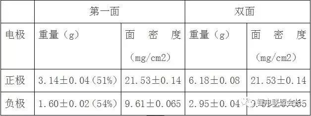
3. After the positive electrode is pulled, perform the following steps:
Cut Large Pieces Cut Small Pieces Gauzes (Materials) Baking After rolling the lug welded pole tabs, perform the following steps:
Tailored Small Pieces Tablets (Materials) Baking Rolled Tabs Welding
.4, rolling requirements

5, the film program
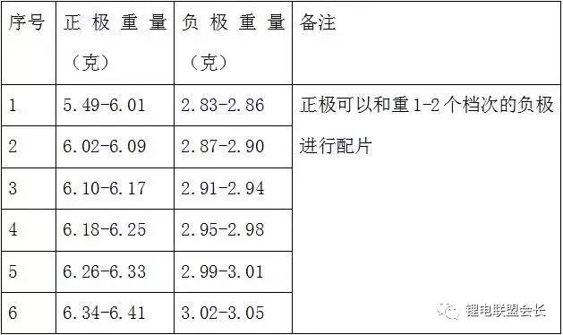
6, pole piece baking

Remarks: The vacuum degree of the vacuum system is -0.095-0.10Mpa; The protection gas is high purity nitrogen, the gas pressure is greater than 0.5Mpa
7, very ear production
a) Positive electrode:
The positive tab is ultrasonically welded at the positive tab. The end of the aluminum strip is flush with the edge of the pole piece.
b) Negative electrode:
Nickel strip size: 0.10 × 3.0 × 48mm, nickel strip spot welding directly with the spot welder, the required number of spot welding points is 8 points on the right side of the nickel strip and the right side of the negative plate, the end of the nickel strip and the edge of the pole piece flush.
8 Diaphragm size: 0.025×44.0×790±5mm
9 needle width: 22.65±0.05mm
10 core: After the battery is wound, first attach the 24mm wide transparent adhesive tape to the bottom of the battery, and then cold press twice with the flattening machine.
11 Requirements before entering the shell
The adhesive tape is 1:10.0×38.0±1.0mm, and the adhesive tape is evenly distributed on both sides of the core;
Adhesive tape 2: 10.0 × 38.0 ± 1.0mm, nickel strips in the center of the tape;
Adhesive tape 3: 24.0 × 30.0 ± 2.0mm, adhesive tape distributed evenly on both sides of the core;
The right side of the nickel strip is 7.0 ± 1.0 mm from the right side of the cell.
12 Shell
When using shells, apply both hands simultaneously and slowly insert the cell into the battery case. Do not scratch the cell.
13 negative electrode tab welding
The negative electrode nickel strip and the steel shell are welded with a spot welding machine. To ensure the welding strength, it is forbidden to weld.
14 Laser welding
Laser welding should be carefully clamped, the battery shell and the cover with a good match before welding, pay attention to avoid welding deviation.
15 Battery Vacuum Bake

Remarks:
(1) The vacuum degree of the vacuum system is -0.095~-0.10MPa;
(2) The protective gas is high purity nitrogen, gas pressure> 0.5MPa;
(3) Vacuum nitrogen injection once every hour
16 Injection volume: 2.9±0.1g
Injection room relative humidity: ≤ 30%, temperature: 20 ± 5 °C Sealing tape: 6mm wide red tape, pay attention to wipe the electrolyte at the injection port when glued paper, use 2 rubber bands to fix the cotton in the liquid injection port Department.
17 Formation system
(1) Opening forming process
a) Constant current charge: 40mA x 4h; 80mA x 6h
Voltage limit: 4.00V
b) Check the voltage, battery voltage ≥ 3.90V for sealing, battery voltage <3.9V with 60mA constant current to 3.90 ~ 4.00V after sealing, then hit the ball
c) Battery cleaning, cleaning agent is acetic acid + alcohol
(2) Continuing to become a system
According to the procedure, continue to:
a) Constant current charging (400mA, 4.20V, 10min)
b) Sleep (2min)
c) Constant current charging (400mA, 4.20V, 100 min)
d) Constant voltage charging (4.20V, 20 mA, 150 min)
e) Sleep (30min)
f) Constant current discharge (750mA, 2.75V, 80 min)
g) Sleep (30min)
h) Constant current charging (750mA, 3.80V, 90 min)
j) Constant voltage charging (3.80V, 20 mA, 150 min)
(3) Inspection and demarcation
Follow the steps below to divide the battery:
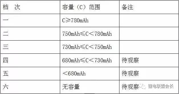
After the battery is removed from the cabinet, the voltage is completely checked, and the battery with a voltage of <3.77V is charged by the program:
(1) Constant current charging (750mA, 3.80V, 10 min)
(2) Dormancy (2min)
(3) Constant current charging (750mA, 3.80V, 30 min)
(4) Constant voltage charging (3.80V, 20 mA, 60 min)
18 Battery Review
After the battery is placed in the cabinet, it is placed in room temperature for 20 days and retested. The procedure is as follows:
a) Shape the battery with a plasticizer;
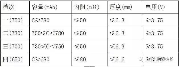
b) Check the battery thickness, voltage, and internal resistance of the battery. The classification method is as follows:
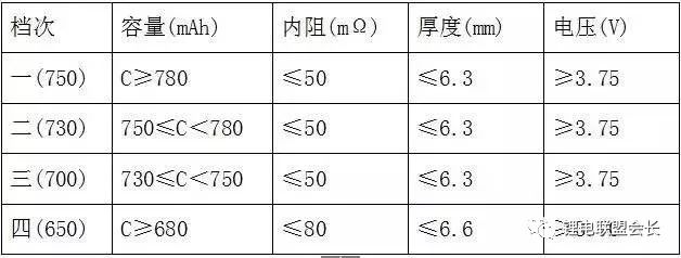
Second, the battery production process
1. (Positive and negative) dry-mixing → Wet-mixing → Rolling paste on the conductive substrate → 3 steps of drying → Winding → Trimming (cut to a certain width) → Rolling → Winding (standby) Dry blending Ball milling The grinding ball is a glass ball or a zirconia ceramic ball;
Wet mixing. Planetary Mixers, whose blades are mounted on 2-3 axes respectively, have better mixing effect. The amount of solvent in the wet mix should be appropriate to form a suitable rheological state for a smooth coating. The roller coating electrode paste must ensure a certain viscosity. The paste is applied on both sides of aluminum foil or copper foil, and the thickness of the coating depends on the battery model. Then, drying is continued through the three heating zones, and NMP (or water) is volatilized from the coating with hot air or dry nitrogen. The solvent can be recovered and reused. Rolling is to increase the density of the coating and to make the thickness of the electrode conform to the size of the battery assembly. The pressure during the rolling stage should be moderate to avoid scattering of the powder during winding.
2, the assembly of the battery
Cylindrical battery assembly process: Insulation bottom ring into the cylinder → winding the battery into the tube → insert the mandrel → welding negative current collector plate in the steel cylinder → insert insulation ring → steel cylinder roll → vacuum drying → liquid injection → combination cap (PTC element, etc.) Welded to the positive electrode lead → Seal → X-ray inspection → Numbering → Formation → Recycling → Aging.
Square battery assembly process flow: Insulation bottom steel box → sheet combination core insert → negative current collector plate welded to steel box → upper sealing gasket → positive current collector plate welded to stem lead → combination cover (PTC element, etc.) Soldered to the lead pole → Positioning of the assembly cover → Laser welding → Vacuum drying → Filling liquid → Sealing → X-ray inspection → Numbering → Chemical conversion → Recycling → Aging.
Assembly process description: Take a cylindrical battery as an example (the basic process of a square battery is the same). Before winding the core into the cylinder, aluminum strips (0.08-0.15 mm thick, 3 mm wide) and nickel strips (0.04-0.10 mm thick, 3 mm wide) were ultrasonically welded to the designated sites of the positive and negative electrode conductive substrates respectively. Stream lead.
The battery separator is generally composed of PE/PP2 or PP/PE/PP 3 layers. The separators are all heat treated at 120°C to increase their resistance and safety.
The positive electrode, the separator, and the negative electrode 3 are stacked and wound into the cylinder. Since the paste electrode is used, the paste material must be well bonded to the substrate to form a high-density electrode, and in particular, the powder should be prevented from passing through the separator. It causes an internal short circuit in the battery.
Before inserting the wound core into the cylinder, placing an insulated bottom into the bottom of the cylinder is designed to prevent internal short circuits in the battery, which is the same for a typical battery.
The electrolyte is generally LiPF6 and a non-aqueous organic solvent. Prior to vacuum injection, the battery is vacuum dried for 24/h to remove moisture and moisture from the battery components to prevent LiPF6 from reacting with water to form HF and shorten the lifetime.
The battery seal adopts sealant, insert gasket, crimping and shrinkage process, the basic principle is the same as alkaline rechargeable battery. After sealing, the battery was cleaned with a mixture of isopropyl alcohol and water to remove oil stains and splashed electrolyte. Use an odor sensor or "sniffer" element to check for battery leakage.
After the entire battery assembly is completed, the battery shall use X-ray to identify whether the internal structure of the battery is normal, check the battery core, cracks in the steel shell, solder joints, and whether there is a short circuit, etc., and eliminate the battery with the above defects to ensure the battery quality.
The last step is chemical conversion. The battery is charged for the first time and a protective film is formed on the anode. This is called the solid electrolyte interlayer (SEI). It prevents the anode from reacting with the electrolyte and is the key to safe operation, high capacity, and long life of the battery. Elements. The battery is aged for 2-3 weeks after several cycles of charge and discharge, and the micro short-circuited battery is removed. After the capacity is sorted and packed, it becomes a product.
Third, the battery performance
1, electrical properties:
(1) Rated capacity: 0.5C discharge, single battery discharge time not less than 2h, battery discharge time not less than 1h54min (95%);
(2) 1C discharge capacity: 1C discharge, single cell discharge time is not less than 57min (95%), the battery discharge time is not less than 54min (90%);
(3) Low-temperature discharge capacity: 0.5C discharge at -20 ï‚°C, and the discharge time of the monomer or battery pack is not less than 1h12min (60%);
(4) High-temperature discharge capacity: 0.5C discharge at 55 ï‚°C, single cell discharge time is not less than 1h54min (95%), battery discharge time is not less than 1h48min (90%);
(5) Charge holding and recovering capability: full power is set aside for 28 days at room temperature, the charge holding discharge time is not less than 1h36min (80%), and the charge recovery discharge time is not less than 1h48min (90%);
(6) Storage performance: The single cell or battery pack subjected to the storage test should be selected from the production date of less than 3 months, and be charged 50% to 60% of the capacity before storage, at an ambient temperature of 40°C ± 5°C, relative humidity. 45% to 75% of the environment is stored for 90 days. After the storage period expires, the battery pack is taken out, and is left fully charged with 0.2C for 1 hour, and then discharged to the termination voltage at a constant current of 0.5C. The above test can be repeated 3 times, and the discharge time is not less than 1h12min (60%);
(7) Cycle life: The battery or battery pack is charged with 0.2C, and the 0.5C discharge is used for the cycle. When two consecutive discharge capacities are lower than 72min (60%), the test is stopped, and the cycle life of the single battery is not less than 600 cycles. Group cycle life not less than 500 times;
(8) Shelf life at high temperature: Shelf life should be selected from single-cell batteries with a production date of less than three months. Shelf life should be charged to 50% ± 5% before shelving, and then at ambient temperature of 55°C ± 2 It is set aside for seven days under Article C. After 7 days, the battery was taken out and left for 2 to 5 hours at an ambient temperature of 20°C ± 5°C. The battery was discharged to the termination voltage at 0.5C, and charged at 0.2C after 0.5h. After being allowed to stand for 0.5h, it was discharged to a termination voltage at a constant current of 0.5C. This capacity was used as recovery capacity. The above steps were one week cycle until the discharge time of one week was less than 72 minutes (60%) and the test was completed. Shelf life is not less than 56 days (8-week cycle).
2, safety performance
(1) Continuous charge: Charge the cell with a constant current of 0.2 ItA. When the voltage of the cell reaches the charge limit voltage, charge it with a constant voltage and maintain it for 28 days. After the test is completed, no leakage, no loss, no Cracked, no fire, no explosion (equivalent to a full floating charge).
(2) Overcharge: The single cell is charged with constant current and constant current source at 3C, and the voltage will reach 10V and then transferred to constant voltage until the battery explodes or catches fire or the charging time is 90min or the surface temperature of the battery is stable (within 45min. When the temperature difference is ≤ 2  C), stop charging, the battery should not cause fire or explosion (3C10V); charge the battery pack with a constant current source at 0.5 ItA, and the voltage reaches n × 5V (n is the number of series cells) Transfer to constant voltage charging until the battery pack explodes or catches fire or the charging time is 90 minutes or the temperature of the battery pack surface is stable (temperature difference within 45 minutes ≤ 2 C). The battery should stop charging or exploding when it stops charging.
(3) Forced discharge (reverse charge): The cell is discharged to a termination voltage with a constant current of 0.2 ItA, and then the battery is charged with 1 ItA current, and the charge time is not less than 90 minutes. The battery should not cause fire, Do not explode; Discharge one of the cells of the battery pack to the termination voltage, and the rest are fully charged batteries. Discharge the battery with a constant current of 1 ItA until the voltage of the battery pack is 0V. The battery should not ignite or explode. .
(4) Short-circuit test: Short-circuit the single cell battery by external short circuit for 90min, or when the battery surface temperature is stable (temperature difference within 45min ≤ 2C), the external line resistance should be less than 50mΩ, and the battery should not burn or explode; The positive and negative electrodes of the group are connected with a copper wire less than 0.1Ω until the battery voltage is less than 0.2V or the surface temperature of the battery pack is stable (within a temperature difference of ≤2°C within 45min). The battery should not catch fire or explode.
3, mechanical properties
(1) Extrusion: The single cell is placed in the middle of two extrusion planes and the pressure is gradually increased to 13 kN. The cylindrical cell extrusion direction is perpendicular to the longitudinal axis of the cylinder axis. The square cell extrudes the wide and narrow sides of the cell. . Each battery can only accept one squeeze. The test results shall comply with the provisions of 4.1.2.1. A steel rod with a diameter of 15 cm was placed on the battery pack to press the battery pack against the wide and narrow sides of the battery pack and squeezed to 85% of the original size of the battery pack for 5 minutes. Each battery pack received only one extrusion.
(2) Acupuncture: The unit cell is placed in a steel fixture and penetrated with a steel pin of φ3mm to φ8mm from the direction perpendicular to the battery plate (the steel needle stays in the battery) for 90 minutes, or the surface of the battery. The test is stopped when the temperature is stable (temperature difference within ≤ 2°C within 45 min).
(3) Impact on heavy objects: Place the unit cell on a steel flat surface and lay it on the center of the battery with a steel rod with a diameter of 15.8mm. The longitudinal axis of the steel bar is parallel to the plane, so that the weight of 9.1kg can be from 610mm. Highly free fall on the steel rod in the center of the battery; when the single cell is cylindrical, the impact direction is perpendicular to the longitudinal axis of the cylinder; when the single cell is square, it will hit the wide and narrow sides of the cell, each battery only Can receive a crash.
(4) Mechanical shock; The battery or battery pack is fixed to the test equipment using a rigid mounting method that supports the battery or all the mounting surfaces of the battery pack. Each of the three mutually perpendicular directions is subjected to an equivalent impact. At least one direction must be guaranteed perpendicular to the wide face of the battery or battery pack. Each impact is performed as follows: within the first 3ms, the minimum average acceleration is 735m/s2, and the peak acceleration should be 1225 m/s2 and 1715 m/s. Between s2.
(5) Vibration: The battery or the battery pack is directly mounted or mounted on the vibration table through a jig for vibration test. The test conditions were a frequency of 10 Hz to 55 Hz, an acceleration of 29.4 m/s2, a XYZ sweep frequency of 10 cycles in each direction, and a sweep rate of 1 oct/min.
(6) Free fall: The single cell or battery pack is freely dropped from a height (minimum point height) of 600 mm to a 20 mm thick hardwood board on the concrete floor, once in each of three directions from XYZ. After the free fall.
4, environmental adaptability
(1) High-temperature baking: The single cell is placed in a high-temperature explosion-proof box and heated up to 130° C. at a heating rate of (5±2 C)/min, and kept at this temperature for 10 minutes.
(2) High-temperature storage: Place the cell or battery in an oven of 75±2°C for 48 hours. The battery should be leak-proof, non-flat, non-broken, non-pyresteric, and non-explosive.
(3) Low pressure: (UL standard).
Second, the production of lithium batteries and their performance;
First, the battery production parameters

1, the pole piece size

2, pull the pulp process
a) Current collector size
Positive electrode (aluminum foil), intermittent coating
Negative electrode (copper foil), intermittent coating
b) Pulling weight requirements
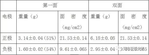
3. After the positive electrode is pulled, perform the following steps:
Cut Large Pieces Cut Small Pieces Gauzes (Materials) Baking After rolling the lug welded pole tabs, perform the following steps:
Tailored Small Pieces Tablets (Materials) Baking Rolled Tabs Welding
.4, rolling requirements

5, the film program
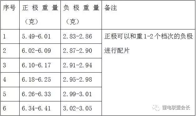
6, pole piece baking

Remarks: The vacuum degree of the vacuum system is -0.095-0.10Mpa; The protection gas is high purity nitrogen, the gas pressure is greater than 0.5Mpa
7, very ear production
a) Positive electrode:
The positive tab is ultrasonically welded at the positive tab. The end of the aluminum strip is flush with the edge of the pole piece.
b) Negative electrode:
Nickel strip size: 0.10 × 3.0 × 48mm, nickel strip spot welding directly with the spot welder, the required number of spot welding points is 8 points on the right side of the nickel strip and the right side of the negative plate, the end of the nickel strip and the edge of the pole piece flush.
8 Diaphragm size: 0.025×44.0×790±5mm
9 needle width: 22.65±0.05mm
10 core: After the battery is wound, first attach the 24mm wide transparent adhesive tape to the bottom of the battery, and then cold press twice with the flattening machine.
11 Requirements before entering the shell
The adhesive tape is 1:10.0×38.0±1.0mm, and the adhesive tape is evenly distributed on both sides of the core;
Adhesive tape 2: 10.0 × 38.0 ± 1.0mm, nickel strips in the center of the tape;
Adhesive tape 3: 24.0 × 30.0 ± 2.0mm, adhesive tape distributed evenly on both sides of the core;
The right side of the nickel strip is 7.0 ± 1.0 mm from the right side of the cell.
12 Shell
When using shells, apply both hands simultaneously and slowly insert the cell into the battery case. Do not scratch the cell.
13 negative electrode tab welding
The negative electrode nickel strip and the steel shell are welded with a spot welding machine. To ensure the welding strength, it is forbidden to weld.
14 Laser welding
Laser welding should be carefully clamped, the battery shell and the cover with a good match before welding, pay attention to avoid welding deviation.
15 Battery Vacuum Bake

Remarks:
(1) The vacuum degree of the vacuum system is -0.095~-0.10MPa;
(2) The protective gas is high purity nitrogen, gas pressure> 0.5MPa;
(3) Vacuum nitrogen injection once every hour
16 Injection volume: 2.9±0.1g
Injection room relative humidity: ≤ 30%, temperature: 20 ± 5 °C Sealing tape: 6mm wide red tape, pay attention to wipe the electrolyte at the injection port when glued paper, use 2 rubber bands to fix the cotton in the liquid injection port Department.
17 Formation system
(1) Opening forming process
a) Constant current charge: 40mA x 4h; 80mA x 6h
Voltage limit: 4.00V
b) Check the voltage, battery voltage ≥ 3.90V for sealing, battery voltage <3.9V with 60mA constant current to 3.90 ~ 4.00V after sealing, then hit the ball
c) Battery cleaning, cleaning agent is acetic acid + alcohol
(2) Continuing to become a system
According to the procedure, continue to:
a) Constant current charging (400mA, 4.20V, 10min)
b) Sleep (2min)
c) Constant current charging (400mA, 4.20V, 100 min)
d) Constant voltage charging (4.20V, 20 mA, 150 min)
e) Sleep (30min)
f) Constant current discharge (750mA, 2.75V, 80 min)
g) Sleep (30min)
h) Constant current charging (750mA, 3.80V, 90 min)
j) Constant voltage charging (3.80V, 20 mA, 150 min)
(3) Inspection and demarcation
Follow the steps below to divide the battery:
After the battery is removed from the cabinet, the voltage is completely checked, and the battery with a voltage of <3.77V is charged by the program:
(1) Constant current charging (750mA, 3.80V, 10 min)
(2) Dormancy (2min)
(3) Constant current charging (750mA, 3.80V, 30 min)
(4) Constant voltage charging (3.80V, 20 mA, 60 min)
18 Battery Review
After the battery is placed in the cabinet, it is placed in room temperature for 20 days and retested. The procedure is as follows:
a) Shape the battery with a plasticizer;
b) Check the battery thickness, voltage, and internal resistance of the battery. The classification method is as follows:
Second, the battery production process
1. (Positive and negative) dry-mixing → Wet-mixing → Rolling paste on the conductive substrate → 3 steps of drying → Winding → Trimming (cut to a certain width) → Rolling → Winding (standby) Dry blending Ball milling The grinding ball is a glass ball or a zirconia ceramic ball;
Wet mixing. Planetary Mixers, whose blades are mounted on 2-3 axes respectively, have better mixing effect. The amount of solvent in the wet mix should be appropriate to form a suitable rheological state for a smooth coating.滚涂电æžè†ä½“è¦ä¿è¯ä¸€å®šçš„粘度, è†ä½“涂于é“箔或铜箔的两é¢, 而涂层的厚度å–å†³äºŽç”µæ± çš„åž‹å·ã€‚然åŽå†ç›¸ç»§é€šè¿‡3ä¸ªåŠ çƒåŒºè¿›è¡Œå¹²ç‡¥, NMP(或水)从涂层ä¸éšçƒç©ºæ°”或干燥氮气æµåŠ¨è€ŒæŒ¥å‘, 溶剂å¯ä»¥å›žæ”¶å†åˆ©ç”¨ã€‚辊压是为了æ高涂层的密度, 并使电æžåŽšåº¦èƒ½ç¬¦åˆç”µæ± 装é…的尺寸, 辊压阶段的压力è¦é€‚ä¸, 以å…å·ç»•æ—¶ç²‰æ–™æ•£è½ã€‚ (欢饮关注:锂电è”盟会长公众å·ï¼‰
2ã€ç”µæ± 的组装
åœ†æŸ±ç”µæ± çš„è£…é…工艺æµç¨‹ï¼šç»ç¼˜åº•åœˆå…¥ç’→å·ç»•ç”µèŠ¯å…¥ç’→æ’入芯轴→焊负æžé›†æµç‰‡äºŽé’¢ç’→æ’å…¥ç»ç¼˜åœˆâ†’é’¢ç’滚线→真空干燥→注液→组åˆå¸½ï¼ˆPTC元件ç‰ï¼‰ç„Šåˆ°æ£æžå¼•æžä¸Šâ†’å°å£â†’X射线检查→编å·â†’化æˆâ†’循环→陈化。
æ–¹å½¢ç”µæ± è£…é…工艺æµç¨‹ï¼šç»ç¼˜åº•å…¥é’¢ç›’→片状组åˆç”µèŠ¯å…¥ç’→负æžé›†æµç‰‡ç„ŠäºŽé’¢ç›’→上密å°åž«åœˆâ†’æ£æžé›†æµç‰‡ç„ŠäºŽæ†å¼•æžâ†’组åˆç›–(PTC元件ç‰ï¼‰ç„Šåˆ°æ—‹å¼•æžä¸Šâ†’组åˆç›–定ä½â†’激光焊接→真空干燥→注液→密å°â†’X射线检查→编å·â†’化æˆâ†’循环→陈化。
装é…å·¥è‰ºè¯´æ˜Žï¼šä»¥åœ†æŸ±å½¢ç”µæ± ä¸ºä¾‹ï¼ˆæ–¹å½¢ç”µæ± åŸºæœ¬è¿‡ç¨‹ç›¸åŒï¼‰ã€‚å·ç»•èŠ¯å…¥ç’以å‰, å°†é“æ¡ï¼ˆ0.08—0.15㎜厚ã€3㎜宽)和é•æ¡ï¼ˆ0.04—0.10㎜厚, 3㎜宽)分别用超声波焊接在æ£ã€è´Ÿæžå¯¼ç”µåŸºä½“的指定处作为集æµå¼•æžã€‚
ç”µæ± éš”è†œä¸€èˆ¬é‡‡ç”¨PE/PP2层或PP/PE/PP 3层组æˆ, 隔膜都是ç»è¿‡120℃çƒå¤„ç†è¿‡çš„, ä»¥å¢žåŠ å…¶é˜»æ¢æ€§å’Œæ高其安全性。
æ£æžã€éš”膜ã€è´Ÿæž3者å åˆåŽå·ç»•å…¥ç’, 由于采用涂è†ç”µæž, 故必须让è†ä½“æ料与基体结åˆå¾—好, 以形æˆé«˜å¯†åº¦ç”µæž, 特别è¦é˜²æ¢æŽ‰ç²‰, 以å…其穿é€éš”è†œè€Œå¼•èµ·ç”µæ± å†…éƒ¨çŸè·¯ã€‚
在å·ç»•ç”µèŠ¯æ’入钢ç’以å‰, 放一个ç»ç¼˜åº•å…¥é’¢ç’底部是为了防æ¢ç”µæ± 内部çŸè·¯è¿™å¯¹äºŽä¸€èˆ¬ç”µæ± 都是相åŒçš„。
电解质一般采用LiPF6å’Œéžæ°´æœ‰æœºæº¶å‰‚, 在真空注液以å‰,ç”µæ± è¦çœŸç©ºå¹²ç‡¥24/h, ä»¥é™¤åŽ»ç”µæ± ç»„åˆ†ä¸çš„水分和潮气, 以å…LiPF6与水å应形æˆHF而缩çŸå¯¿å‘½ã€‚
ç”µæ± å¯†å°é‡‡ç”¨æ¶‚密å°èƒ¶ã€æ’入垫圈ã€å·è¾¹åŠ æ–é¢æ”¶ç¼©è¿‡ç¨‹,基本原ç†ä¸Žç¢±æ€§å¯å……ç”µæ± ç›¸åŒã€‚å°å£ä»¥åŽ, ç”µæ± è¦ç”¨å¼‚丙醇和水的混åˆæ¶²é™¤åŽ»æ²¹æ±¡ç‰©å’Œæº…出的电解液, 然åŽå†å¹²ç‡¥ã€‚使用一ç§æ°”å‘³ä¼ æ„Ÿå™¨æˆ–â€œ 嗅探器â€å…ƒä»¶æ£€æŸ¥ç”µæ± æ¼æ¶²æƒ…况。
æ•´ä¸ªç”µæ± è£…é…完æˆä»¥åŽ, ç”µæ± è¦ç”¨Xå°„çº¿é‰´å®šç”µæ± å†…éƒ¨ç»“æž„æ˜¯å¦æ£å¸¸, 对于电芯ä¸æ£ã€é’¢å£³è£‚ç¼ã€ç„Šç‚¹æƒ…况ã€æœ‰æ— çŸè·¯ç‰è¿›è¡Œæ£€æŸ¥, æŽ’é™¤æœ‰ä¸Šè¿°ç¼ºé™·çš„ç”µæ± , ç¡®ä¿ç”µæ± è´¨é‡ã€‚
最åŽä¸€é“å·¥åºæ˜¯åŒ–æˆ, ç”µæ± ç¬¬1次充电, 阳æžä¸Šå½¢æˆä¿æŠ¤è†œ, 称为固体电解质ä¸é—´ç›¸å±‚(SEI), 它能防æ¢é˜³æžä¸Žç”µè§£è´¨å应, å¹¶æ˜¯ç”µæ± å®‰å…¨æ“作ã€é«˜å®¹é‡ã€é•¿å¯¿å‘½çš„关键è¦ç´ ã€‚ç”µæ± ç»è¿‡å‡ 次充放电循环以åŽé™ˆåŒ–2—3周, 剔去微çŸè·¯ç”µæ± , å†è¿›è¡Œå®¹é‡åˆ†é€‰åŒ…装åŽå³æˆä¸ºå•†å“了。
三ã€ç”µæ± 的性能

1ã€ç”µæ€§èƒ½ï¼š
(1) é¢å®šå®¹é‡ï¼š0.5C放电,å•ä½“ç”µæ± æ”¾ç”µæ—¶é—´ä¸ä½ŽäºŽ2hï¼Œç”µæ± ç»„æ”¾ç”µæ—¶é—´ä¸ä½ŽäºŽ1h54min(95%);
(2)1C放电容é‡ï¼š1C放电,å•ä½“ç”µæ± æ”¾ç”µæ—¶é—´ä¸ä½ŽäºŽ57min(95%ï¼‰ï¼Œç”µæ± ç»„æ”¾ç”µæ—¶é—´ä¸ä½ŽäºŽ54min(90%);
(3)低温放电容é‡ï¼š-20ï‚°C下0.5C放电,å•ä½“æˆ–ç”µæ± ç»„æ”¾ç”µæ—¶é—´å‡ä¸ä½ŽäºŽ1h12min(60%);
(4)高温放电容é‡ï¼š55ï‚°C下0.5C放电,å•ä½“ç”µæ± æ”¾ç”µæ—¶é—´ä¸ä½ŽäºŽ1h54min(95%ï¼‰ï¼Œç”µæ± ç»„æ”¾ç”µæ—¶é—´ä¸ä½ŽäºŽ1h48min(90%);
(5) è·ç”µä¿æŒåŠæ¢å¤èƒ½åŠ›ï¼šæ»¡ç”µå¸¸æ¸©ä¸‹æç½®28天,è·ç”µä¿æŒæ”¾ç”µæ—¶é—´ä¸ä½ŽäºŽ1h36min(80%),è·ç”µæ¢å¤æ”¾ç”µæ—¶é—´ä¸ä½ŽäºŽ1h48min(90%);
(6)储å˜æ€§èƒ½ï¼šè¿›è¡Œè´®å˜è¯•éªŒçš„å•ä½“ç”µæ± æˆ–ç”µæ± ç»„åº”é€‰è‡ªç”Ÿäº§æ—¥æœŸä¸è¶³3个月的,贮å˜å‰å……50%~60%的容é‡ï¼Œåœ¨çŽ¯å¢ƒæ¸©åº¦40℃±5ï‚°C,相对湿度45%~75%的环境贮å˜90天。贮å˜æœŸæ»¡åŽå–å‡ºç”µæ± ç»„ï¼Œç”¨0.2C充满电æç½®1håŽï¼Œä»¥0.5Cæ’æµæ”¾ç”µè‡³ç»ˆæ¢ç”µåŽ‹,上述试验å¯é‡å¤æµ‹è¯•3次,放电时间ä¸ä½ŽäºŽ1h12min(60%);
(7ï¼‰å¾ªçŽ¯å¯¿å‘½ï¼šç”µæ± æˆ–ç”µæ± ç»„é‡‡ç”¨0.2C充电,0.5C放电åšå¾ªçŽ¯ï¼Œå½“è¿žç»ä¸¤æ¬¡æ”¾ç”µå®¹é‡ä½ŽäºŽ72min(60%)时åœæ¢æµ‹è¯•ï¼Œå•ä½“ç”µæ± å¾ªçŽ¯å¯¿å‘½ä¸ä½ŽäºŽ600æ¬¡ï¼Œç”µæ± ç»„å¾ªçŽ¯å¯¿å‘½ä¸ä½ŽäºŽ500次;
(8)高温æ置寿命:应选自生产日期ä¸è¶³ä¸‰ä¸ªæœˆçš„å•ä½“ç”µæ± çš„è¿›è¡Œé«˜æ¸©æ置寿命试验,进行æç½®å‰åº”å……å…¥50%±5%的容é‡ï¼Œç„¶åŽåœ¨çŽ¯å¢ƒæ¸©åº¦ä¸º55℃±2ï‚°Cçš„æ¡ä¸‹æç½®7天。7天åŽå°†ç”µæ± å–出,在环境温度为20℃±5ï‚°C下æç½®2~5h。先以0.5Cå°†ç”µæ± æ”¾ç”µè‡³ç»ˆæ¢ç”µåŽ‹ï¼Œ0.5håŽæŒ‰0.2C进行充电,é™ç½®0.5h åŽï¼Œå†ä»¥0.5Cæ’æµæ”¾ç”µè‡³ç»ˆæ¢ç”µåŽ‹ï¼Œä»¥æ¤å®¹é‡ä½œä¸ºæ¢å¤å®¹é‡ã€‚以上æ¥éª¤ä¸º1周循环,直至æŸå‘¨æ”¾ç”µæ—¶é—´ä½ŽäºŽ72min(60%),试验结æŸã€‚æ置寿命ä¸ä½ŽäºŽ56天(8周循环)。
2ã€å®‰å…¨æ€§èƒ½
(1)æŒç»å……电:将å•ä½“ç”µæ± ä»¥0.2ItAæ’æµå……电,当å•ä½“ç”µæ± ç«¯ç”µåŽ‹è¾¾åˆ°å……ç”µé™åˆ¶ç”µåŽ‹æ—¶ï¼Œæ”¹ä¸ºæ’压充电并ä¿æŒ28d,试验结æŸåŽï¼Œåº”ä¸æ³„æ¼ã€ä¸æ³„æ°”ã€ä¸ç ´è£‚ã€ä¸èµ·ç«ã€ä¸çˆ†ç‚¸ï¼ˆç›¸å½“于满电浮充)。
(2)过充电:将å•ä½“ç”µæ± ç”¨æ’æµç¨³åŽ‹æºä»¥3Cæ’æµå……电,电压达到10VåŽè½¬ä¸ºæ’åŽ‹å……ç”µï¼Œç›´åˆ°ç”µæ± çˆ†ç‚¸æˆ–èµ·ç«æˆ–充电时间为90minæˆ–ç”µæ± è¡¨é¢æ¸©åº¦ç¨³å®šï¼ˆ45min内温差≤2ï‚°C)时åœæ¢å……ç”µï¼Œç”µæ± åº”ä¸èµ·ç«ã€ä¸çˆ†ç‚¸ï¼ˆ3C10Vï¼‰ï¼›å°†ç”µæ± ç»„ç”¨ç¨³åŽ‹æºä»¥0.5ItAæ’æµå……电,电压达到n×5V(n为串è”å•ä½“ç”µæ± æ•°ï¼‰åŽè½¬ä¸ºæ’åŽ‹å……ç”µï¼Œç›´åˆ°ç”µæ± ç»„çˆ†ç‚¸æˆ–èµ·ç«æˆ–充电时间为90minæˆ–ç”µæ± ç»„è¡¨é¢æ¸©åº¦ç¨³å®šï¼ˆ45min内温差≤2ï‚°C)时åœæ¢å……ç”µï¼Œç”µæ± åº”ä¸èµ·ç«ã€ä¸çˆ†ç‚¸ã€‚
(3)强制放电(åå‘充电):将å•ä½“ç”µæ± å…ˆä»¥0.2ItAæ’æµæ”¾ç”µè‡³ç»ˆæ¢ç”µåŽ‹ï¼Œç„¶åŽä»¥1ItA电æµå¯¹ç”µæ± 进行åå‘充电,è¦æ±‚充电时间ä¸ä½ŽäºŽ90minï¼Œç”µæ± åº”ä¸èµ·ç«ã€ä¸çˆ†ç‚¸ï¼›å°†ç”µæ± 组其ä¸ä¸€åªå•ä½“ç”µæ± æ”¾ç”µè‡³ç»ˆæ¢ç”µåŽ‹ï¼Œå…¶ä½™å‡ä¸ºå……满电æ€çš„ç”µæ± ï¼Œå†ä»¥1ItAæ’æµæ”¾ç”µè‡³ç”µæ± 组的电压为0Væ—¶åœæ¢æ”¾ç”µï¼Œç”µæ± 应ä¸èµ·ç«ã€ä¸çˆ†ç‚¸ã€‚
(4)çŸè·¯æµ‹è¯•ï¼šå°†å•ä½“ç”µæ± ç»å¤–部çŸè·¯90minï¼Œæˆ–ç”µæ± è¡¨é¢æ¸©åº¦ç¨³å®šï¼ˆ45min内温差≤2ï‚°C)时åœæ¢çŸè·¯ï¼Œå¤–部线路电阻应å°äºŽ50mÎ©ï¼Œç”µæ± åº”ä¸èµ·ç«ã€ä¸çˆ†ç‚¸ï¼›å°†ç”µæ± 组的æ£è´Ÿæžç”¨å°äºŽç”µé˜»0.1Î©çš„é“œå¯¼çº¿è¿žæŽ¥ç›´è‡³ç”µæ± ç»„ç”µåŽ‹å°äºŽ0.2Væˆ–ç”µæ± ç»„è¡¨é¢æ¸©åº¦ç¨³å®šï¼ˆ45min内温差≤2ï‚°Cï¼‰ï¼Œç”µæ± åº”ä¸èµ·ç«ã€ä¸çˆ†ç‚¸
3ã€æœºæ¢°æ€§èƒ½
(1)挤压:将å•ä½“ç”µæ± æ”¾ç½®åœ¨ä¸¤ä¸ªæŒ¤åŽ‹å¹³é¢ä¸é—´ï¼Œé€æ¸å¢žåŠ 压力至13kNï¼Œåœ†æŸ±å½¢ç”µæ± æŒ¤åŽ‹æ–¹å‘åž‚ç›´äºŽåœ†æŸ±è½´çš„çºµè½´ï¼Œæ–¹å½¢ç”µæ± æŒ¤åŽ‹ç”µæ± çš„å®½é¢å’Œçª„é¢ã€‚æ¯åªç”µæ± åªèƒ½æŽ¥å—一次挤压。试验结果应符åˆ4.1.2.1çš„è§„å®šã€‚åœ¨ç”µæ± ç»„ä¸Šæ”¾ä¸€ç›´å¾„ä¸º15cmçš„é’¢æ£’å¯¹ç”µæ± ç»„çš„å®½é¢å’Œçª„é¢æŒ¤åŽ‹ç”µæ± ç»„ï¼ŒæŒ¤åŽ‹è‡³ç”µæ± ç»„åŽŸå°ºå¯¸çš„85%,ä¿æŒ5min,æ¯ä¸ªç”µæ± 组åªæŽ¥å—一次挤压。
(2)针刺:将å•ä½“ç”µæ± æ”¾åœ¨ä¸€é’¢åˆ¶çš„å¤¹å…·ä¸ï¼Œç”¨Ï†3mm~φ8mmçš„é’¢é’‰ä»Žåž‚ç›´äºŽç”µæ± æžæ¿çš„æ–¹å‘贯穿(钢针åœç•™åœ¨ç”µæ± ä¸ï¼‰ï¼ŒæŒç»90minï¼Œæˆ–ç”µæ± è¡¨é¢æ¸©åº¦ç¨³å®šï¼ˆ45min内温差≤2℃)时åœæ¢è¯•éªŒã€‚
(3)é‡ç‰©å†²å‡»ï¼šå°†å•ä½“ç”µæ± æ”¾ç½®äºŽä¸€é’¢æ€§å¹³é¢ä¸Šï¼Œç”¨ç›´å¾„15.8mmçš„é’¢æ£’å¹³æ”¾åœ¨ç”µæ± ä¸å¿ƒï¼Œé’¢æ£’的纵轴平行于平é¢ï¼Œè®©é‡é‡9.1kgçš„é‡ç‰©ä»Ž610mm高度自由è½åˆ°ç”µæ± ä¸å¿ƒçš„钢棒上;å•ä½“ç”µæ± æ˜¯åœ†æŸ±å½¢æ—¶ï¼Œæ’žå‡»æ–¹å‘垂直于圆柱é¢çš„纵轴;å•ä½“ç”µæ± æ˜¯æ–¹å½¢æ—¶ï¼Œè¦æ’žå‡»ç”µæ± 的宽é¢å’Œçª„é¢ï¼Œæ¯åªç”µæ± åªèƒ½æŽ¥å—一次撞击。
(4) æœºæ¢°å†²å‡»ï¼›å°†ç”µæ± æˆ–ç”µæ± ç»„é‡‡ç”¨åˆšæ€§å›ºå®šçš„æ–¹æ³•ï¼ˆè¯¥æ–¹æ³•èƒ½æ”¯æ’‘ç”µæ± æˆ–ç”µæ± ç»„çš„æ‰€æœ‰å›ºå®šè¡¨é¢ï¼‰å°†ç”µæ± æˆ–ç”µæ± ç»„å›ºå®šåœ¨è¯•éªŒè®¾å¤‡ä¸Šã€‚åœ¨ä¸‰ä¸ªäº’ç›¸åž‚ç›´çš„æ–¹å‘上å„承å—一次ç‰å€¼çš„冲击。至少è¦ä¿è¯ä¸€ä¸ªæ–¹å‘ä¸Žç”µæ± æˆ–ç”µæ± ç»„çš„å®½é¢åž‚直,æ¯æ¬¡å†²å‡»æŒ‰ä¸‹è¿°æ–¹æ³•è¿›è¡Œï¼šåœ¨æœ€åˆçš„3ms内,最å°å¹³å‡åŠ 速度为735m/s2ï¼Œå³°å€¼åŠ é€Ÿåº¦åº”è¯¥åœ¨1225 m/s2å’Œ1715 m/s2之间。
(5) æŒ¯åŠ¨ï¼šå°†ç”µæ± æˆ–ç”µæ± ç»„ç›´æŽ¥å®‰è£…æˆ–é€šè¿‡å¤¹å…·å®‰è£…åœ¨æŒ¯åŠ¨å°é¢ä¸Šè¿›è¡ŒæŒ¯åŠ¨è¯•éªŒã€‚试验æ¡ä»¶
2500 Puffs Vpae,Mini Disposable E-Cigarette,Rechargeable Disposable Vape,Thick Oil Atomizer Vaporizer Pen
Guangzhou Yunge Tianhong Electronic Technology Co., Ltd , https://www.e-cigarettesfactory.com