Prof. Zhou Ligong's new book "Programming for AMetal Frameworks and Interfaces (Part 1)" introduces the AMetal framework in detail. By reading this book, you can learn highly multiplexed software design principles and development ideas for interface programming. Focus on your own "core domain", change your own programming thinking, and achieve common progress between the company and the individual.
The eighth chapter is to understand AMetal in depth . The content of this article is 8.1 LED universal interface.
Chapter VIII Guide
Programming for a common interface makes the application independent of the specific hardware and can be easily implemented across platforms. But how is the essence of it, how is it achieved?
8.1 LED universal interface
This section will take the LED universal interface as an example to introduce the design method of the general interface in detail.
> > > 8.1.1 Defining interfaces
Reasonable interfaces should be easy to read and have clear responsibilities. The following describes the general methods for defining interfaces in AMetal from three aspects: interface naming, parameters, and return values.
1. Interface naming
In AMetal, all common interfaces start with "am_" followed by the name of the operation object. For the LED control interface, all interfaces should be prefixed with "am_led_".
After the prefix of the interface is defined, you need to consider which functional interfaces are defined, and then complete the interface name according to the function. For LEDs, the core operation is to control the state of the LEDs, to illuminate or extinguish the LEDs, so it is necessary to provide a function to set the LED state, such as:
Am_led_set
Obviously, the status of the LED can be set through this interface. In order to distinguish whether the LED is lit or extinguished, a specific operation needs to be specified by one parameter.
In most applications, it may be necessary to turn the lights on and off frequently. Each time the switch lights need to pass the parameters to the am_led_set() interface to turn the lights on and off, this can be very cumbersome. It is therefore possible to define a dedicated interface for the usual turn-on and turn-off operations, which eliminates the need for additional parameters to distinguish between specific operations. For example, if on and off are used to indicate that the light is turned on and off, respectively, the interface name for turning the light on and off is defined as:
Am_led_on
Am_led_off
In some special applications, such as LED flashing, it may not care whether the specific operation is to turn the light on or off, it only needs to flip the state of the LED. At this point, you can define an interface for toggleing the LED status. The interface name is:
Am_led_toggle
2. Interface parameter
In AMetal, the first parameter of the generic interface represents the specific object to be manipulated. Obviously, a system may have multiple LEDs. The easiest way to determine the LEDs to operate is to assign a unique number to each LED, the ID number, and then determine the LED to be operated by the ID number. The ID number is an integer starting at 0 and its type is int. Based on this, the first parameter of all interfaces is defined as the led_id of type int.
For the am_led_set interface, in addition to using led_id to determine which LEDs to control, you also need to use a parameter to distinguish between lighting the LED or extinguishing the LED. Since it is an alternative operation, the type of this parameter uses the Boolean type: am_bool_t. When the value is true (AM_TRUE), the LED is lit; when the value is false (AM_FALSE), the LED is extinguished. Based on this, the am_led_set interface function prototype containing the parameters is (the return value has not been defined yet):

For the am_led_on, am_led_off, and am_led_toggle interfaces, they have a single responsibility, and only need to specify the control LED to complete the lighting, extinction or flip operation without additional parameters. So for this type of interface, the parameters only need led_id. Its function prototype is as follows:

In fact, in the first parameter of the AMetal universal interface, in addition to using the ID number to represent the specific object of the operation, it is also possible to directly use a pointer to a specific object, or a handle representing a specific object to represent, their role in the essence The above is exactly the same.
3. return value
For the user, after calling the generic interface, you should be able to get the results of this execution, success or failure, or some other useful information. For example, when the interface is called, if the specified led_id exceeds the valid range, since there is no LED device corresponding to led_id, the operation will fail. At this time, an error must be returned to inform the user that the operation failed, and the reason for the failure is that the led_id is not in the valid range. Inside, there is no corresponding LED device.
In AMetal, the result of the interface execution is returned by the return value, and its type is int. The meaning of the return value is: if the return value is AM_OK, the operation is successful; if the return value is negative, the operation fails, and the reason for the failure is based on Return value, find the macro defined in the am_errno.h file, determine the cause of the failure according to the meaning of the macro; if the return value is a positive number, its meaning is related to the specific interface, defined by the specific interface, if there is no special description, it means that it will not return A positive number.
AM_OK is defined in the am_common.h file and is defined as follows:

The error number is defined in the am_errno.h file. The definitions of several common error numbers are detailed in Table 8.1. For example, when the LED universal interface is called, if the led_id is not in the valid range, the led_id does not have a corresponding LED device, and the interface should return -AM_ENODEV. Note: M_ENODEV has a negative sign in front of it to return a negative value.
Table 8.1 Common Error Number Definitions (am_errno.h)
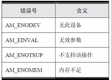
Based on this, the return value of all LED control interfaces is defined as int. The complete definition of the LED control interface is shown in Table 8.2, and the corresponding class diagram is shown in Figure 8.1.
Table 8.2 LED Universal Interface (am_led.h)
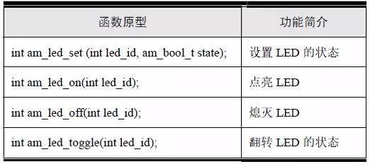
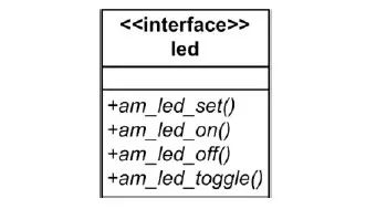
Figure 8.1 LED corresponding class diagram
> > > 8.1.2 Implementing the interface
When the interface definition is complete, you also need to provide the appropriate driver to implement these interfaces in order to use these interfaces to operate the LEDs.
1. Preliminary exploration of the interface
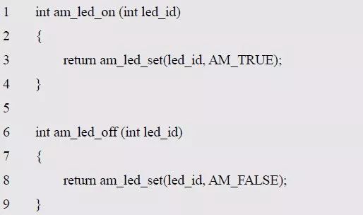
The LED has four general-purpose interface functions, of which the am_led_on() and am_led_off() interfaces are implemented based on the am_led_set() interface. See Listing 8.1 for details.
Listing 8.1 Implementation of the am_led_on() and am_led_off() interfaces
The core of the implementation interface is to implement the am_led_set() and am_led_toggle() interfaces. The general interface is to shield the underlying differences. That is, no matter how the underlying hardware changes, the user can call the general interface operation LED. However, for different hardware circuits, such as GPIO and HC595 control LED hardware circuits, the specific implementation of setting LED status and LED flip is different. The following is a detailed description of the specific implementation of setting the LED status.
For the hardware circuit of the GPIO control LED, when using GPIO to control the two onboard LEDs of AM824-Core, LED0 is connected to PIO0_20 of MCU through J9, and LED1 is connected to PIO0_21 of MCU through J10. Use short circuit to short J9 and J10, then use PIO0_20 and PIO0_21 to control LED0 and LED1. When the pin output is low, it will light the LED. When the pin outputs high level, the LED will be off and the GPIO universal interface will be used directly. The implementation of the am_led_set() interface is detailed in Listing 8.2.
Listing 8.2 Implementation of am_led_set() (GPIO Control LED)
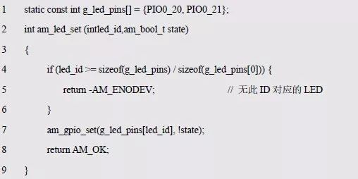
For the hardware circuit of the HC595 control LED, when the MiniPort-595 and MiniPort-LED are used in combination, by controlling the output of the HC595, the effect of controlling the LED to be turned on and off can be achieved. When the corresponding pin outputs a low level, Lights up the LED; when the corresponding output is high, it turns off the LED, and directly uses the HC595 universal interface to implement the am_led_set() interface. See Listing 8.3 for details.
Listing 8.3 Implementation of am_led_set() (HC595 Control LED)
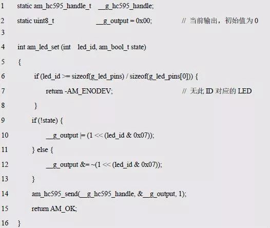
In practical applications, __g_hc595_handle needs to be assigned before it can be used. A comparison between Listing 8.2 and Listing 8.3 reveals that their implementation of setting the LED state is completely different. Obviously, in the same application, the implementation code of an interface can only have one copy, so the implementation shown in Listing 8.2 and Listing 8.3 cannot coexist in an application. In this case, either choose to use the GPIO to control the LED or use the HC595 to control the LED.
2. Abstract LED device class
When using different methods to control LEDs, although they correspond to the implementation methods of am_led_set() and am_led_toggle(), they have the same function, which is their commonality: both need to set the LED state and flip the LED state. The function. Since the implementation code of an interface can only have one copy, their implementation cannot be directly used as the implementation code of the generic interface. To do this, you can abstract their commonalities, that is, abstract into the following two methods:

The abstract method has one more p_cookie parameter than the generic interface. In object-oriented programming, methods in an object can access the object itself through the invisible pointer p_this, referencing some of its own private data. In C, you need an explicit declaration, where p_cookie has the same effect.
In order to save memory space, put all abstract methods in a structure to form a virtual function table, such as:

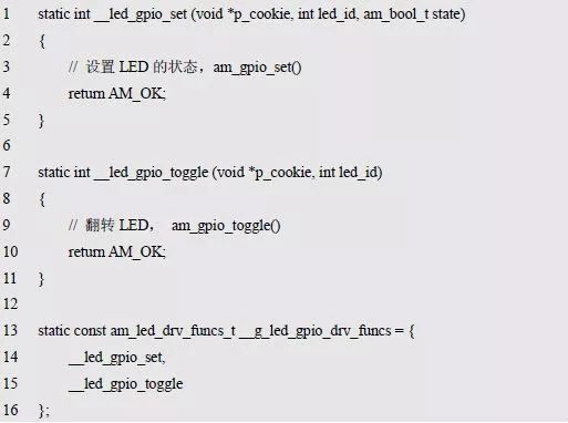
This defines a virtual function table that contains two methods for setting the state of the LED and flipping the LEDs. For different hardware devices, these two methods can be implemented according to their own characteristics. The pseudo code for the GPIO control LED is detailed in Listing 8.4. The pseudo code for the HC595 control LED is detailed in Listing 8.5.
Listing 8.4 Implementation of the abstract method (GPIO Control LED)
Listing 8.5 Implementation of the abstract method (HC595 Control LED)
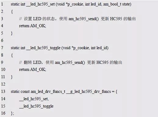
Obviously, __g_led_gpio_drv_funcs and __g_led_hc595_drv_funcs are specific implementations of controlling LEDs using GPIO and HC595, respectively. They are formally two different structural constants that can coexist in the same system. When there is a driver for different hardware, in the implementation of the am_led_set() interface, you need to find the corresponding driver according to the actual situation, and then call the pfn_led_set method implemented in it. When the pfn_led_set() method is called, since the first argument to the method is p_cookie, p_cookie represents the specific object. In fact, the driver function and p_cookie together uniquely identify a specific LED device. Based on this, the driver function and p_cookie can be defined together to form a new LED device type. which is:

Where p_funcs is a pointer to a table that drives the virtual function, for example, pointing to __g_led_gpio_drv_funcs or __g_led_hc595_drv_funcs, where p_cookie is a pointer to the device, the first argument passed to the driver function.
At this point, in the implementation of the am_led_set() interface, there is no need to complete the actual operation of setting the LED state, just call the pfn_led_set method in the device. The sample program is shown in Listing 8.6.
Listing 8.6 am_led_set() implementation (1)
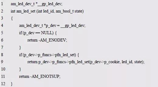
Assume that the LED device is the device pointed to by the global variable __gp_led_dev and shows the calling form of the pfn_led_set method. In fact, there are often more than one LED device. For example, devices that use GPIO to control LEDs and devices that use the HC595 to control LEDs need to manage multiple LED devices in the system. Since their specific number cannot be determined, a one-way linked list is required for dynamic management. Add a p_next member to am_led_dev_t to point to the next device. which is:

At this point, multiple LED devices in the system are managed in the form of a linked list. So in the implementation of the general interface, how to determine which LED device to use? When defining a common interface, the led_id is used to distinguish different LEDs. If an LED device is bound to the corresponding led_id of the device, in the implementation of the universal interface, the corresponding LED device can be found according to the led_id, and then the driver is used. The corresponding method provided in the LED completes the operation.
Obviously, an LED device may contain multiple LEDs. In the AM824-Core, the GPIO controls 2 LEDs and the HC595 controls 8 LEDs. If two devices are used at the same time, there are 10 LEDs in the whole system, numbered 0~9. In general, all LED numbers in a device are continuous. For example, two LED devices are numbered 0~1, 2~9. To get the number of all LEDs in an LED device, just know the start number and end number of the LED. For this purpose, define the LED_id information corresponding to the LED device as:

A new p_info pointer to the LED information is added to the device to facilitate finding the corresponding LED device based on the led_id in the general interface implementation, namely:

Based on this, the implementation of the am_led_set() function is detailed in Listing 8.7.
Listing 8.7 am_led_set() implementation (2)
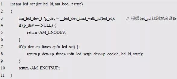
Among them, the role of __led_dev_find_with_id() is to traverse the device list and compare it with the ID information in each device to find the LED device corresponding to led_id. For details, see Listing 8.8.
Listing 8.8 Finding LED devices with the specified led_id
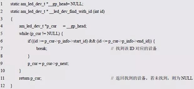
Where __gp_head is a global variable, initially NULL, indicating that there are no LED devices in the system at the beginning. For the same reason, the implementation of the am_led_toggle() interface can be obtained. See Listing 8.9 for details.
Listing 8.9 am_led_toggle() implementation
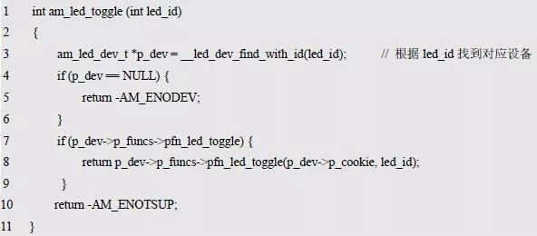
At this point, all common interfaces are implemented. Since there are currently no LED devices, __led_dev_find_with_id() is NULL and the return value of the generic interface is always -AM_ENODEV.
In order for the universal interface to operate to a specific and effective LED, an effective LED device must be added to the system. Depending on the type of LED device type, the correct assignment of p_funcs, p_cookie, and p_info is required when adding a device. The assignment of these members requires specific LED device objects, such as devices with GPIO control LEDs. To do this, you can provide an interface to the drive to add LED devices. such as:

In order to facilitate the driver to directly add a device, to avoid direct operation of each member of the LED device, the members that need to be assigned are passed to the interface function through parameters, and the implementation is detailed in Listing 8.10.
Listing 8.10 Adding LED Devices to the System

The program first determines whether the ID is a valid range by judging whether the start LED number and the end LED number of the new device are already present in the system, and ensuring that the IDs of the added LED devices do not conflict, that is, the uniqueness of the LED number is ensured. Then assign each member of the device, and finally add the new device to the list header by a total of 2 lines of code from lines 21 to 22 of Listing 8.10.
Obviously, in the specific LED device driver implementation, the device is added to the system using the am_led_dev_add() interface, so that the user can use the LED universal interface to operate to a specific LED.
In the above analysis process, the LED device class is defined, in which the implementation of the LED universal interface is completed, and the relationship can be represented by a class diagram, as shown in Figure 8.2.
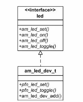
Figure 8.2 Abstract LED device class
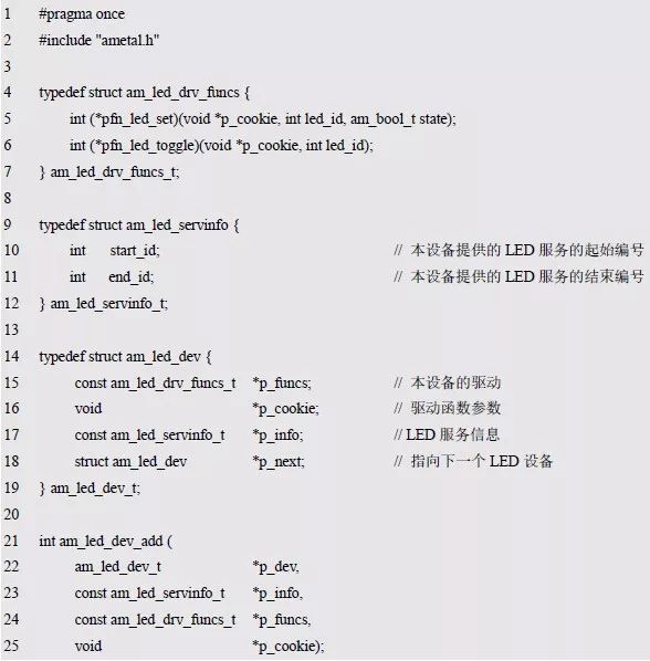
There are abstract methods pfn_led_set and pfn_led_toggle in LED devices. These two abstract methods exist in the LED device class in the form of virtual function tables. Because of the abstract method, the LED device class is an abstract class, which itself cannot be instantiated directly, and must be implemented by its derived concrete class. For ease of reference, the contents of the interface file am_led_dev.h of the LED device are shown in Listing 8.11.
Listing 8.11 am_led_dev.h file contents
3. Specific LED equipment
The abstract LED device class defined earlier contains two abstract methods: pfn_led_set and pfn_led_toggle. In order for the user to operate the LED through the LED universal interface, two abstract methods must be implemented based on the actual hardware connection, and then the specific device is added to the system device linked list.
The following is an example of the driving implementation of the GPIO control LED and the driving implementation of the HC595 control LED. The general method of LED device driver development is described. If there are other types of LED control circuits, you can add a custom LED driver according to this method.
(1) GPIO control LED driver implementation
The core function of a specific LED device is to implement the method defined in the abstract device class. First, a specific device class should be derived based on the abstract device class. The class diagram is shown in Figure 8.3.
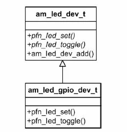
Figure 8.3 Specific Device Class (GPIO)
Specific LED device classes can be defined directly. such as:

Am_led_gpio_dev_t is the specific LED device class. With this type, you can use this type to define a specific LED device instance:

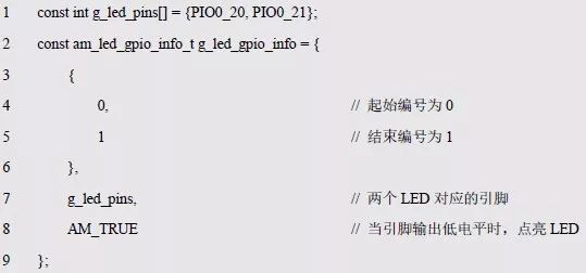
When using GPIO to control the LED, you need to know the corresponding pin information and the level information of the LED lighting. In order to modify the configuration, this information is often transmitted to the driver by the user. In addition, you need to provide the LED device ID information, including the start ID and end ID, to determine a unique ID for each LED in the device. Based on this, device-related information that needs to be provided by the user can be stored in a new structure type as device information that needs to be provided by the user. which is:

For the two onboard LEDs of AM824_Core, if the number is 0~1, you can use this type to define the corresponding device instance information as follows:
In order to facilitate the direct finding of the corresponding device information through the device, a pointer to the device information is often directly maintained in the device class. which is:

Obviously, before using the GPIO to control the LED, the pin needs to be initialized to the output mode. In addition, after the initialization is completed, a specific LED device needs to be added to the system to facilitate operation of the LED using the general interface. This work is usually done in the driver's initialization function. The prototype of the initialization function is:

Where p_dev points to a device of type am_led_gpio_dev_t and p_info is a pointer to instance information of type am_led_gpio_info_t, which is called as follows:

The implementation of the initialization function is detailed in Listing 8.12.
Listing 8.12 Initialization Function Implementation (GPIO Control LED)
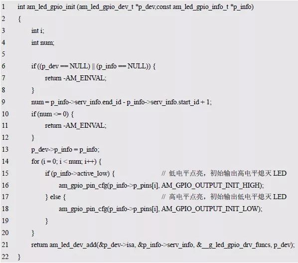
In the program, the number of LEDs is first obtained by the start number and end number of the LED. Since the number of pins of the GPIO is equal to the number of LEDs, the number of GPIO pins is obtained. All pins are then configured for output mode and are illuminated depending on whether they are low or low, initially causing all LEDs to be off. Finally, specific LED devices are added to the system via the am_led_dev_add() function.
When adding an LED device, the ID information of the LED directly uses the ID information in the device information. The implementation of the abstract method uses the method implemented in __g_led_gpio_drv_funcs (the definition is detailed in Listing 8.4), and the p_cookie is directly set to point to the device itself. Pointer, because of this, in the implementation of the abstract method, the p_cookie parameter is a pointer to the device itself, and can obtain specific device-related information, such as GPIO information, through p_cookie, thereby implementing LED related operations, and improving the program list 8.4. The abstract method of implementation is detailed in Listing 8.13.
Listing 8.13 Implementation of the abstract method (GPIO Control LED)

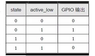
In the implementation of abstract methods, p_cookie is first converted to a pointer to a specific device by type casting. Then through it to find the corresponding pin information, in order to achieve LED related operations. In the implementation of setting the LED state, the XOR (^) budget is cleverly used. Because the value of active_low is exactly opposite to the actual lighting level, that is, if active_low is AM_TRUE, it indicates that the output is low, and vice versa, the output is lit. The values ​​of state and active_low will affect the output level of this GPIO. The true level table of GPIO output level and state and active_low is shown in Table 8.3. Thus, when state is the same as active_low, GPIO outputs 0; when state is different from active_low, GPIO outputs 1, which is exactly the XOR relationship.
Table 8.3 GPIO Output Value Added Table
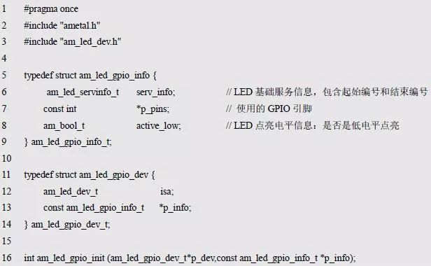
For ease of reference, the contents of the LED device interface file am_led_gpio.h are shown in Listing 8.14.
Listing 8.14 am_led_gpio.h file contents
(2) HC595 control LED drive implementation
Similarly, first derive a specific device class based on the abstract device class. The class diagram is shown in Figure 8.4, which can directly define the specific LED device class:

Am_led_hc595_dev_t is a specific LED device class. When this type is available, you can use this type to define a specific LED device instance:

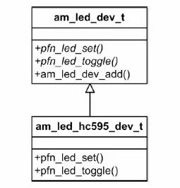
Figure 8.4 Specific Equipment Category (HC595)
When using the HC595 to control the LED, you need to know the LED and HC595 related information, such as the level information of the LED lighting and the number of HC595. Although the MiniPort-595 has only one HC595, as a general-purpose driver, these basic extensions should be considered so that the driver can support as many hardware circuits as possible.
In particular, each output of the HC595 is a complete output. For a single HC595, it can only output complete 8-bit data per output. It cannot output 1 bit of data separately. The control of the LED is performed on a single LED. Therefore, in order to control one LED, it does not affect other LEDs, and the output of other bits must be kept unchanged. This requires real-time saving of the current output. In order to save the output information of all current HC595s, the user needs to provide a buffer. Area, the size of the buffer is equal to the number of HC595.
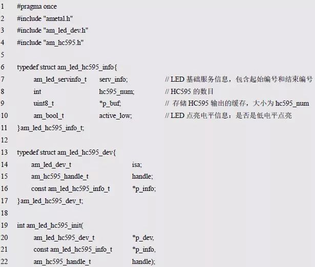
In addition, you need to provide ID information that includes a start ID and an end ID. Based on this, device-related information that needs to be provided by the user can be stored in a new structure type as device information that needs to be provided by the user:

For the joint use of MiniPort-595 and MiniPort-LED, there are 8 LEDs in total. If the assigned number is 2~9, you can use this type to define the corresponding device instance information as follows:
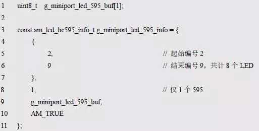
For the same reason, it is necessary to maintain a pointer to device information in the device class. In addition, since the HC595 driver handle is required to transfer data when using the HC595 driver, the user also needs to provide a handle of 595. The handle needs to be saved to the device:

Note that since the handle often needs to be obtained by dynamically calling the instance initialization function, for example, the handle of the HC595 can be obtained by the following statement:

The device information is not changed after the system is started. It can be defined as a constant. Therefore, the handle is often provided by the user separately and is not stored in the device information.
Obviously, before using the GPIO to control the LEDs, you need to complete the assignment of each member in the device and turn off all LEDs. In addition, after the initialization is complete, you need to add specific LED devices to the system. This work is usually done in the driver's initialization function. The prototype of the initialization function is:

Where p_dev is a pointer to an instance of the am_led_hc595_dev_t type, and p_info is a pointer to the instance information of the am_led_hc595_info_t type, which is called as follows:

The implementation of the initialization function is detailed in Listing 8.15.
Listing 8.15 Initialization Function Implementation (HC595 Control LED)

First set the value in the cache to a value that causes all LEDs to go out, then use am_hc595_send() to output the values ​​in the cache so that all LEDs are off. Finally, specific LED devices are added to the system via the am_led_dev_add() function.
When adding an LED device, the ID information of the LED directly uses the ID information in the device information. The implementation of the abstract method uses the method implemented in __g_led_hc595_drv_funcs (the definition is detailed in Listing 8.5), and the p_cookie is set directly to point to the device itself. Pointer, because of this, in the implementation of the abstract method, the p_cookie parameter is a pointer to the device itself, and can obtain specific device-related information, such as HC595 handle, HC595 cache, etc. through p_cookie, thereby implementing LED related operations and improving the program. The abstract method implemented in Listing 8.5 is detailed in Listing 8.16.
Listing 8.16 Implementation of the abstract method (HC595 Control LED)

In the implementation of abstract methods, p_cookie is first converted to a pointer to a specific device by type casting. Then through it to find relevant information, in order to achieve LED related operations. For ease of reference, the contents of the LED device interface file am_led_hc595.h are shown as shown in Listing 8.17.
Listing 8.17 am_led_hc595.h file contents
16MM Key Switches
In the past 30 years, our company has been striving to create a high-quality and high-reliability 16mm power key switch. In order to enhance the competitive advantage in the world, our company has dozens of imported advanced testing equipment and has a complete ISO 9001 quality management system. The series On Off Key Switch products are strictly screened and repeatedly tested to provide customers with reliable products for the purpose of making customers rely on our quality.

One of the the most competitive factor of our key lock switch is that we have design a bran-new modal, ie, S301 serious , which is the only exclusive security key switch in the switches industry. Furthermore, the voltage and electricity of 16MM key switches is stronger, could supply bigger equipment and machines, like Metal Switches, Automotive Switches, Rocker Switches and Slide Switches.

Quality assurance of our 16 mm key switch power lock: In order to meet the requirements of customers in Japan, Europe,the United States and the globe, our 16mm key switches have passed the European and American environmental protection RoHS certification, and can provide customers with a full range of key switch SGS material analysis report, UL certification and other Relevant third-party testing and certification.
16Mm Key Switches,16Mm Push Button Switch ,16Mm Key Switch On Off,3 Position Slide Switch
YESWITCH ELECTRONICS CO., LTD. , https://www.yeswitches.com