High-frequency microwave switch is one of the most important basic electromechanical components in various military systems engineering, and it is an electromechanical component that realizes specific functions for switching microwave signals in various harsh environments and specific spaces. Satellite communications in China Electronic countermeasures, radar engineering, and various measuring instruments are widely used. The purpose of this paper is to introduce the design idea of ​​the microwave switch transmission part, and to discuss the microwave switch structure using the MicroWave Studio simulation design calculation.
2, microwave switch high frequency characteristicsNo. Operating frequency (GHz) Standing wave ratio (max) Isolation (min) Insertion loss (max)
10-11.15800.15
21-41.25800.20
34-81.35700.35
48-12.41.45600.45
3, microwave switch worksThe microwave switch introduced in this paper is a single pole double throw transfer switch. The working principle of the switch is to use the electromagnetic drive system to generate the thrust generated on the rectangular microstrip line after being excited, so that a set of rectangular microstrip line displacements that are disconnected can be implemented. The high-frequency coaxial socket is turned on, and the other group is under the action of the spring force of the rectangular microstrip line and the high-frequency coaxial socket is separated to achieve signal disconnection. When the stimulus is removed, the switch is restored to the original state. The switch shares a high-frequency input RFIN. (See Figure 1)
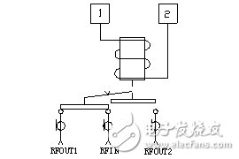
Figure I. Microwave Switch Operation Diagram
3.1, microwave transmission structure design
The transmission structure is the core part of the switch, mainly composed of reeds, bases, SMA sockets and other components (see Figure 2). The contact between the reed and the SMA socket ferrule is achieved by pushing the driving rod by the electromagnetic driving system. The positive pressure of the two is equal to the switching force of the electromagnetic driving system minus the elastic force of the spring. Because the switching force of the electromagnetic driving system is far greater than the spring The elastic force forms enough mechanical retention force to ensure the reliable contact of the switch, and the separation of the reed and the SMA socket ferrule is achieved by the compression spring pushing the reset rod driving reed and the SMA socket ferrule to separate. The contact pairs are alternately converted; the electromagnetic drive system adopts the teeterboard structure, which has high reliability, long service life and high sensitivity.
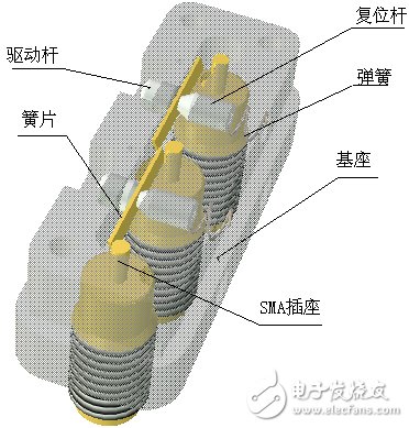
Figure 2, transmission structure diagram
3.2, structural parameters design
This switch converts the transmission path of the high-frequency path through the coaxial line - the microstrip line (strip line) - the coaxial line. On each length unit of the transmission line, the characteristic impedance should be equal to the nominal value of 50Ω as much as possible in order to reduce the reflection as much as possible. Therefore, in the design of structural parameters, the structural parameters of the high-frequency channel of the switch can be divided into two types: the design of a standard symmetric microstrip line and the design of a coaxial socket. The size of each key component can be determined initially by calculation. Three-dimensional simulation design laid the foundation.
3.2.1, the design of a standard symmetrical microstrip line
The important parameters controlling the characteristic impedance of a symmetric microstrip line are the conductor (reed) width, the dielectric thickness, and the dielectric constant of the substrate material. The symmetric microstrip line is a rectangular coaxial transmission line. It is mainly composed of a cavity, a cover plate, and a microstrip line. When calculating, it ignores the influence of high-frequency input and output sockets, and determines the standard symmetrical microstrip line according to the ideal state. For calculation convenience, The rectangular coaxial transmission line is regarded as a symmetric standard microstrip transmission line, and the relevant major dimensions of the symmetric band transmission line in terms of electrical transmission are shown in Figure 3:
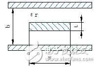
Figure 3, Symmetric Standard Microstrip End View
The size of the symmetric standard microstrip facet can be preliminarily determined according to the following table.
![]() t/b
t/b
0.01t/b
0.05t/b
0.10t/b
0.20t/b
0.30t/b
0.50
W/b
50Ω1.407741.296061.173270.953890.757390.41725
3.2.2, coaxial socket design
Both the input socket and the output socket are SMA-type coaxial sockets. Therefore, the structure of the socket interface part is standard, and the calculation formula of its internal structure using the characteristic impedance of the coaxial line is as follows.
![]() ……………………1
……………………1
In the formula, Zc is the characteristic impedance, the input and output socket requirements are 50Ω, εr is the relative permittivity of the medium, the relative dielectric constant of the air is 1, the relative permittivity of the PTFE support is 2.2, D is external The inner diameter of the conductor, d is the outer diameter of the inner conductor.
4, microwave switch three-dimensional simulation designThe use of three-dimensional high-frequency electromagnetic field analysis software for modeling, simulation and calculation of microwave switches can improve the success rate of product design, obtain the performance data that the design may achieve, and further optimize the model to achieve the required performance indicators, and then arrange the production of Samples whose performance specifications are very close to the design requirements.
4.1ã€CST MICROWAVE STUDIO Software Introduction
MicroWave Studio (Microwave Studio) is the three-dimensional high-frequency electromagnetic field simulation and calculation software of German CST company. It is one of the three mainstream high-frequency electromagnetic field soft simulation calculations in the world. It has powerful modeling function, rich material library and model. The library, which can simulate three-dimensional electromagnetic fields in waveguides, space, microstrip lines, coaxial lines, and cavities, facilitates the simulation and optimization of antennas, filters, waveguide devices, and connectors.
4.2, simulation calculation
The transmission of high-frequency microwaves is achieved through the transmission system of certain special structures. The high-frequency signal of the switch is the transmission mode from the coaxial line to the rectangular strip line to the coaxial line, and there are multiple conductors throughout the transmission. Cross-section abrupt changes and right angles, impedance discontinuities are unavoidable: the structure of the entire transmission channel leads to the presence of discontinuous capacitances; the mechanical dimensions of the part will cause the characteristic impedance to drift; and the field shape of the electromagnetic field will produce discontinuities in the characteristic impedance. The theoretical calculation can only determine the mechanical dimensions of some parts, so it must be simulated and optimized by means of three-dimensional high-frequency electromagnetic field simulation calculation software. First of all, the switch structure is simplified, and the corresponding switch high-frequency transmission structure model is established in the MicroWave Studio software (see Figure 4). Secondly, the parameters are set. All the material parameters are set in the following table, and the background material is set to PEC, ie For metal conductors, set the test frequency range from 0.04 MHz to 12.4 GHz, and set the center frequency at 5 GHz. Set the ports in the next step: Set the connectors at both ends to 50 Ω. Set the solution conditions: Frequency 5 GHz, 10 iterations The maximum error of 0.01, Fast sweep mode, 0.04MHz ~ 12.4GHz, divided into 50 copies.
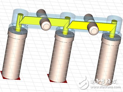
Figure 4. Three-dimensional simulation model established in MicroWave Studio
Material parameters in the model
Name nameRelaTIve pemitTIvityRelaTIve permeabilityBulk conducTIvity
Air air1.00061.00000040
Teflon(tm) 2.0510
Copper copper10.99999158000000siemens/m
Aluminum aluminum11.000002133000000siemens/m
4.3, simulation results
We have carried out simulation calculations for various schemes of coaxial and stripline patching and stripline structure dimensions to finally determine stripline and pedestal cavity dimensions (see Figure 5).
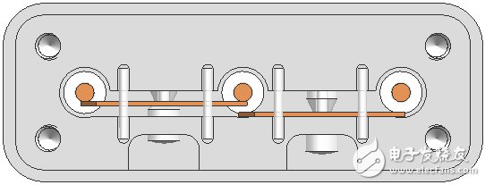
Figure 5. Stripline and pedestal cavity structure
4.4 Test results
The optimized calculation data is used in the design of the product. After the sample is produced, the high-frequency indexes of some samples meet the requirements of the indicator (see Figure 6). However, some of the samples do not meet the requirements. The analysis is mainly Due to the discontinuity of the impedance caused by the failure of the mechanical tolerances of the parts during the machining of the switch parts.
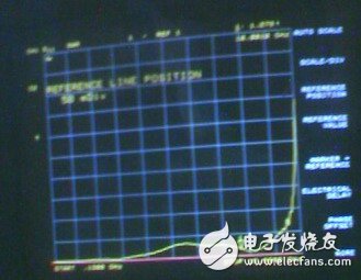
Figure 6, sample test results
5. Concluding remarksThe design of this switch preliminarily determines the nominal dimensions of the relevant part structure of the microwave transmission channel by adopting the theoretical design. After the simulation of three-dimensional high-frequency electromagnetic field simulation software modeling, the final product structure size is determined. Since the microwave switch is essentially a non-uniform coaxial line with connection mechanism, conversion mechanism and other devices, it has obvious unevenness in four places compared with the uniform coaxial line: connector interface matching area, coaxial socket From the standard symmetric microstrip line and the standard symmetric microstrip line to the coaxial socket transition area, uniform support area, and conductor size transition area. In these places, there is a change in the diameter of the conductor or in the shape of the conductor, and therefore a discontinuous capacitance appears, causing reflections. Therefore, it is necessary to verify and correct part of the structural dimensions of the part by processing the actual sample for many test measurements in order to achieve the required Product performance.
Variable Frequency Drive,Variable Frequency Drive For Motor,Three Phase 400V Ac Drive,Variable Frequency Drive For Lift
Zhejiang Kaimin Electric Co., Ltd. , https://www.ckmineinverter.com