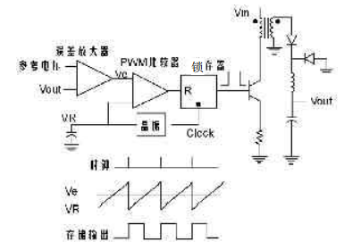
The switching power circuit is divided into current mode control and voltage mode control. The UC3846 is a chip with peak current mode control. For the voltage mode control shown in Figure 1, the advantages are: only the voltage loop, single loop control is easy to design and analyze; the waveform amplitude slope is large, so the noise is small, the work is stable; when the multi-module output, the low-impedance output can provide a good Interactive control. The disadvantage is that the disturbance of the grid or load must be converted into output disturbance to be fed back by the voltage loop, so the system responds slowly; the output LC filter circuit adds two poles to the system, which requires a zero point in the compensation network or a low turnaround. The main pole of the frequency; the loop gain varies with the input voltage, so the compensation network design is more complicated.

Figure 1 voltage mode control
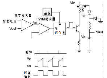
The current mode control shown in Figure 2 is applied in the BUCK circuit. Compared with the voltage mode control, the clock signal only operates the power supply at a fixed frequency. The other input of the PWM comparator replaces the crystal with the signal obtained from the inductor current. The analog signal of the inductor current exceeds the value Ve of the error amplifier output, and the pulse width is turned off.

Figure 2 Current Mode Control
The advantage of current mode control is that the rising slope of the inductor current is Vin-Vo, so the waveform of the inductor current can respond quickly to changes in the grid voltage, avoiding the response delay and gain varying with the input voltage; the error amplifier is used Control the output current instead of the output voltage, so the inductor can be regarded as the current source of the error voltage control. The output filter circuit can be simplified to a single-pole circuit (output capacitor parallel load resistor), which makes the compensation circuit simplified and has more specific voltage mode control. Larger gain bandwidth; the output clamp of the error amplifier reaches the pulse-by-pulse current limit; current sharing is easy to achieve when the power modules are connected in parallel.
All significant shortcomings of voltage mode control are overcome by current mode control, so current mode control is gaining more and more attention and application. However, pay attention to the following problems when applying current mode control: when the duty ratio is greater than 50%, the control loop is unstable, and slope compensation is required at this time; the control regulation circuit is based on the signal obtained from the inductor current, so the oscillation of the power part It is easy to introduce noise into the control circuit.
Chip structure
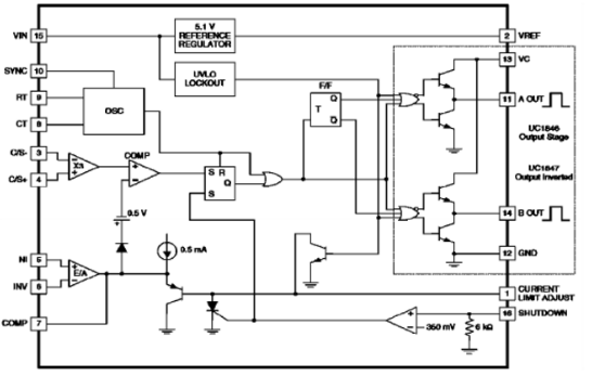
Figure 3 UC3846 structure diagram
As can be seen from Figure 3, the UC3846 obtains an inductor current or a switch current signal by using a differential current sense amplifier with a fixed magnification of 3 (its input is less than 1.2V), which is even at low detection voltages. Can maintain high noise suppression. The other end of the PWM comparator is connected to the voltage error amplifier. The output of the voltage error amplifier is used as the given signal. The output of the voltage error amplifier is clamped to the V pin 1+0.7 by the current limiting adjustment terminal (pin 1), thus completing the pulse by pulse. The purpose of current limiting. When the differential current sense amplifier detects the switch current instead of the inductor current, the detection current will have a large peak leading edge due to the parasitic capacitance discharge of the switch tube, which may cause the current detection latch and the PWM circuit to malfunction, so we are The current detection input is RC filtered.
Aluminum Cell Phone Stand, Durable Cellphone,Desk Cell Phone Stand Holder Aluminum Phone Dock Cradle,etc.
Shenzhen Chengrong Technology Co.ltd is a high-quality enterprise specializing in metal stamping and CNC production for 12 years. The company mainly aims at the R&D, production and sales of Notebook Laptop Stands and Mobile Phone Stands. From the mold design and processing to machining and product surface oxidation, spraying treatment etc ,integration can fully meet the various processing needs of customers. Have a complete and scientific quality management system, strength and product quality are recognized and trusted by the industry, to meet changing economic and social needs .

Aluminum Vell Phone Stand,Aluminum Cell Phone Desk Stand,Cell Phone Holder For Stand,Cell Phone Stands
Shenzhen ChengRong Technology Co.,Ltd. , https://www.laptopstandsupplier.com