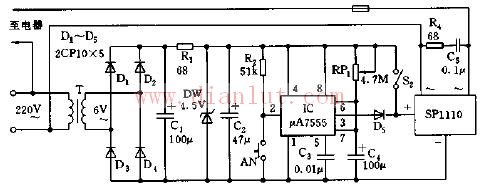
As shown in the figure, the AC timing switch control circuit. The controller is composed of a step-down rectifier circuit, a one-shot timer, an AC solid state relay, and the like. The buck rectifier circuit provides a DC voltage to the entire controller.
The single-stable circuit composed of IC (555) and W1, R2, C4, etc. has a timing time of td=1.1Rw1C4, and the longest timing time corresponding to the graphical parameters is about 30 minutes. The specific timing can be adjusted by adjusting W1. achieve.
When the switch AN is pressed, the IC is set because the 2 pin is low, and the high level of the 3 pin output turns on the AC output terminal of the AC solid state relay SP110, and the load is turned on accordingly, and the timing starts. When the IC is timed out, the 3 pin outputs a low level, so that the AC output of the SP110 is disconnected, the load is also disconnected, and the timing ends.
The control function of the circuit can realize the corresponding automatic timing under the condition of alternating current.
