1 Introduction
In recent years, the national energy conservation situation has become increasingly severe. Energy conservation has become one of the topics of general concern in the society. Various large-scale coal companies have also used various advanced technologies to reduce production costs, and the demand for frequency converters that drive high-voltage motors is in the coal industry. It's getting bigger and bigger.
The main fan is the most important equipment in the coal mine ventilation system and is the most important part of coal mine safety production. From the point of view of the motor running at the power frequency, the motor is kept in the power frequency running state for a long time. When the user needs to adjust the air volume and the wind pressure, it is mainly achieved by adjusting the fan blade angle or the throttle opening degree, which is essentially through sacrificing the fan. The way of efficiency to reduce the wind pressure, thus causing unnecessary energy waste, the angle deviation of the blade when cutting fluid or doing work on the damper increases the mechanical loss of the fan, does not achieve the purpose of economic operation, and is uninterrupted 24h a day Operation, according to the requirements of wind conditions and operating conditions of late mining, the power of the designed fan and motor is usually much larger than the operating power required for normal production of the coal mine. The fan design has a large margin, and the fan has been operating under light loads for quite a long time. Therefore, there is an extremely serious phenomenon of large horse-drawn cars in the coal mine ventilation system, and energy waste is very prominent. Therefore, it is imperative that the main fan fan's frequency conversion energy-saving transformation.
2 Situation at the scene
Shanxi Baoxian Lanxian Baoxin Coal Mine is located in Guxian County, Shanxi Province. The main fan is responsible for the ventilation of the entire mine. It requires high safety and stability. Once the turbine is shut down, the whole mine will not be able to be normally produced in a short period of time. The air volume is adjusted by adjusting the size of the damper opening. Regardless of the air volume required for production, the fan must run at full speed, and the change in operating conditions will cause the energy to be lost due to the air doing work on the damper. Not only the control accuracy is low, but also a large amount of energy waste and equipment loss are caused, resulting in increased production costs, shortened equipment life, and high equipment maintenance and maintenance costs. In response to this situation, electrical technicians have repeatedly investigated and decided. The RNHV intelligent high-voltage frequency converter produced by Shanghai Renault Technology Co., Ltd. was used for energy-saving transformation.
3 Principle of Energy Saving of the Main Fan
According to fluid mechanics, P (power) = Q (air flow) ╳ H (pressure), the air flow rate Q is proportional to the primary speed of the rotational speed N, the pressure H is proportional to the square of the rotational speed N, and the power P is proportional to the cube of the rotational speed N The main fan control is to adjust the air volume by changing the size of the damper opening. Its essence is to change the size of the gas resistance in the pipeline to change the air volume. Because the rotational speed of the fan is constant, its characteristic curve remains unchanged. When the damper is fully open, the air volume is Qa, and the pressure head of the fan is Ha. If the throttle is closed, the pipe resistance characteristic curve changes. At this time, the air volume is Qb, and the pressure head of the fan goes to Hb. The increase in head pressure is: ΔHb = Hb-Ha. The energy loss then occurs: ΔPb = ΔHb × Qb.
By changing the speed of the fan to adjust the air volume, the essence is to change the air volume by changing the energy of the delivered gas. Because only the speed changes, the throttle opening does not change and the pipe resistance characteristic curve remains unchanged. At rated speed, the air flow is Qa and the indenter is Ha. When the rotation speed decreases, the characteristic curve changes and the air volume becomes Qc. At this time, assuming that the air volume Qc is controlled to the air volume Qb in the damper control mode, the air volume of the fan will be reduced to Hc. Therefore, the pressure head is reduced compared to the throttle control mode: ΔHc=Ha-Hc. This saves energy: ΔPc = ΔHc × Qb. Compared with the throttle control mode, the energy saved is: P = ΔPb + ΔPc = (ΔHb - ΔHc) × Qb.
Comparing these two methods, we can see that under the same air volume, the speed control avoids the energy loss caused by the increase of the indenter and the increase of pipe resistance under the throttle control. When the air volume is reduced, the speed control makes the head significantly lower, so it only requires a much smaller power loss than the throttle control.
From the above, it can be seen that when it is required to adjust the air volume to decrease, the rotation speed N can decrease proportionally, and at this time, the output power P of the shaft is established and the relationship decreases. That is, the relationship between the power consumption of the fan motor and the rotational speed is approximately established.
4 Features of Renault High-voltage Inverter
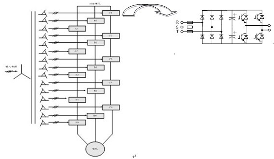
RNVH-A series high-voltage inverter adopts multi-cell series multi-level technology and belongs to high-voltage source inverter, which can directly input 6KV/10KV and output directly to 6KV/10KV. Taking the 6KV series as an example, each phase consists of 5 power units connected in series. Each power unit is powered by the secondary isolation coil of the input isolation transformer, and the output three phases form a Y-shape, which directly powers the 6KV motor.

6KV high voltage frequency converter system topology
The power unit structure is AC-DC-AC. Each power unit is mainly composed of an input fuse, a three-phase full-bridge rectifier, a capacitor bank, an IGBT inverter bridge, a DC bus, and a bypass circuit, and also includes a control drive circuit. Each unit is a three-phase input, single-phase output PWM-type inverter. The output voltage state is 1, 0, -1, and five different units per phase can generate 11 different voltage levels.
This structure uses a low-voltage device to achieve high-voltage output, reducing the pressure requirements on the power device, and the harmonic pollution of the power grid is very small. With high input power factor, it is not necessary to use input harmonic filter and power factor compensation device, and the output waveform is close to sine wave. There is no characteristic of additional heat generation, torque ripple, noise, dv/dt and common mode voltage caused by harmonics. Without adding an output filter, an ordinary asynchronous motor can be used.
Each power unit is powered by a set of secondary windings of a phase-shifting transformer, and the AC input is converted to DC by a three-phase full-bridge rectifier. The electronic control unit receives the PWM signal sent by the main control system and outputs the PWM voltage waveform by controlling the operating state of the IGBT. The monitoring circuit monitors the status of the IGBT and DC bus in real time and feeds the status back to the master control system.
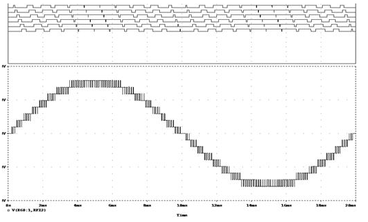
The PWM voltage waveforms output by the N power units of each phase are superimposed to generate a multiple phase voltage waveform of 2N+1 voltage steps. The PWM waveforms output by the five power units and the phase voltage waveforms after superposition are shown in the figure:

Inverter unit output waveform and phase voltage waveform overlay
The main control system includes the main control board and its input and output interfaces. The main control board adopts 32-bit DSP, CPLD and other large-scale integrated circuits and surface welding technology, and the system has extremely high reliability. The main control board establishes a communication link with all power units through the optical fiber communication system, transmits PWM signals to each power unit, and returns status information of each power unit. Through the touch screen, the system can run, stop, reset and set the function parameters and record inquiries. The I/O interface of the main control board is used to implement external communication in the terminal control mode. The main functions are: system terminal reset, run/stop control, external analog frequency setting, system status, and operating frequency. The input of the main control board also includes a sampling signal that controls the power supply and the operating current.
The electrical control centered on Siemens S7-200 as a high-reliability programmable logic controller (PLC), supplemented by relays, switches, etc., responsible for the internal logic control of the drive and the external interface with the user. The PLC mainly performs the following functions: exchanges data such as given frequency, operating frequency, output current and function number with the main control system; monitors the status of the main control system, such as ready, running, and faults; handles the switching of the control power of the inverter and the switch of the bypass cabinet switch , interlock, fan, cabinet door, transformer temperature and other signals; processing the user's high-voltage switch signals, control command signals, and provide the user with the inverter running status and parameters, so the interface operating language is all in Chinese, the application software is also Chinese version Content is user-friendly and offers free software upgrades for life.
5 Frequency Converter Modification
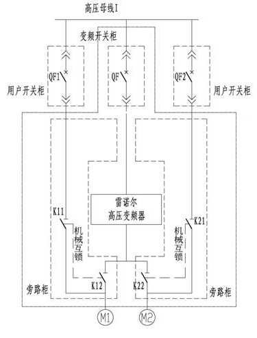
The main fan is a counter-rotating axial fan. One fan is used to prepare one fan. Each fan contains two motors. One frequency converter is used to drive two motors simultaneously. The external one is equipped with a manual one-to-two bypass switching cabinet. . The main circuit is shown in the figure.

Main circuit diagram
During normal operation, manual knife gates K12 and K22 are closed, power frequency knife gates K11 and K21 are disconnected, frequency conversion switch QF is closed, and the frequency converter drives two motors at the same time to operate, and the air volume is adjusted by adjusting the output frequency of the inverter.
When the frequency conversion fault occurs, the variable frequency switch cabinet QF is disconnected, K11 and K21 are closed, K12 and K22 are disconnected, and the system resumes the power frequency operation of the original operation mode.
K11 and K12, K21, and K22 cannot be closed at the same time, and they are mechanically interlocked.
The frequency conversion fault signal and the frequency conversion switchgear are also interlocked to realize the high-voltage fault continuous jump function.
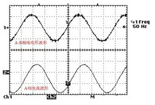
Renault high-voltage frequency converter is very friendly to the motor. After the field transformation is completed, the output waveform measurement of the inverter is carried out without high harmonics, as shown in the figure.

6 Benefits after retrofit
After the frequency conversion reform, the dampers are all turned on, the operating frequency is about 40Hz, and the operating current is 23A, which fully meets the production ventilation requirement in the mine, and the speed of air volume adjustment is improved, the user operation procedure is simplified, the frequency converter operation is very stable, and the fan startup is reduced. The impact of the time has produced tremendous economic benefits.
The energy-saving benefits are as follows:
When the power frequency is running, the damper opening is about 2m, and the total operating current of the two motors is 35A.
Power-frequency runtime power and one-day power consumption:
P = 1.732 x 10 x 35 x 0.85 = 515.27 kW
When the inverter is running, the damper is fully opened and the operating current is 21A. The inverter regulates the fan speed to meet the air volume requirement.
Frequency conversion runtime power and one-day power consumption:
P variable = 1.732 x 10 x 21 x 0.96 = 349.17 kW
Power saving rate: (P work - P change) / P work = (515.27-349.17)/515.27 = 32.2%.
Saving electricity calculations:
The electricity price is calculated as 0.6 yuan/kWh, and the power frequency is 24h:
515.27×24×0.6=7419.89.
Frequency conversion 24h power consumption fee:
349.17 × 24 × 0.6 = 5028.05 yuan.
After the conversion of frequency conversion, electricity savings on the day:
7419.89-5028.05=2391.84 yuan.
The number of days of effective operation in a year is calculated as 280 days, and the electricity cost is saved annually:
2391.84 × 280 = 669715.2 yuan.
7 Conclusion
After the frequency conversion of the main fan of Lanhua Baoxin Coal Mine in Guxian County of Shanxi Province, not only has a good energy-saving effect been achieved, but also the stability of the entire ventilation system has been raised to a large level. With the country’s increasing emphasis on energy conservation and emission reduction, coal mining enterprises reduce production costs through various measures, and frequency conversion energy-saving technologies have also received increasing attention. The RNHV high-voltage inverters manufactured by Shanghai Renault Technology Co., Ltd. are also required. It will play an increasingly important role in contributing to the energy conservation and emission reduction business of the entire country.
16 Port USB 1U Cabinet Charger
Our new 16 port USB1U built -in charger provides the fastest charging, and is supported by tablet computers and other battery -intensive personal electronic equipment! Adopting a compact and lightweight design, without occupying position space, can be a variety of offices, restaurants, retail, education or personal devices configuration. The USB has a built -in fast charging to up to 200 watt charging power, making it very suitable for most tablet computers, smartphones, portable battery charging equipment, and most other devices that meet the USB 2.0. Our new 16 port USB charging hub station has inventory and provides free transportation for free!
Hub USB Charging Station 16 Ports 200W, 16 Port USB Charger 1U Cabinet, 16-Port USB-C HUB
shenzhen ns-idae technology co.,ltd , https://www.best-charger.com