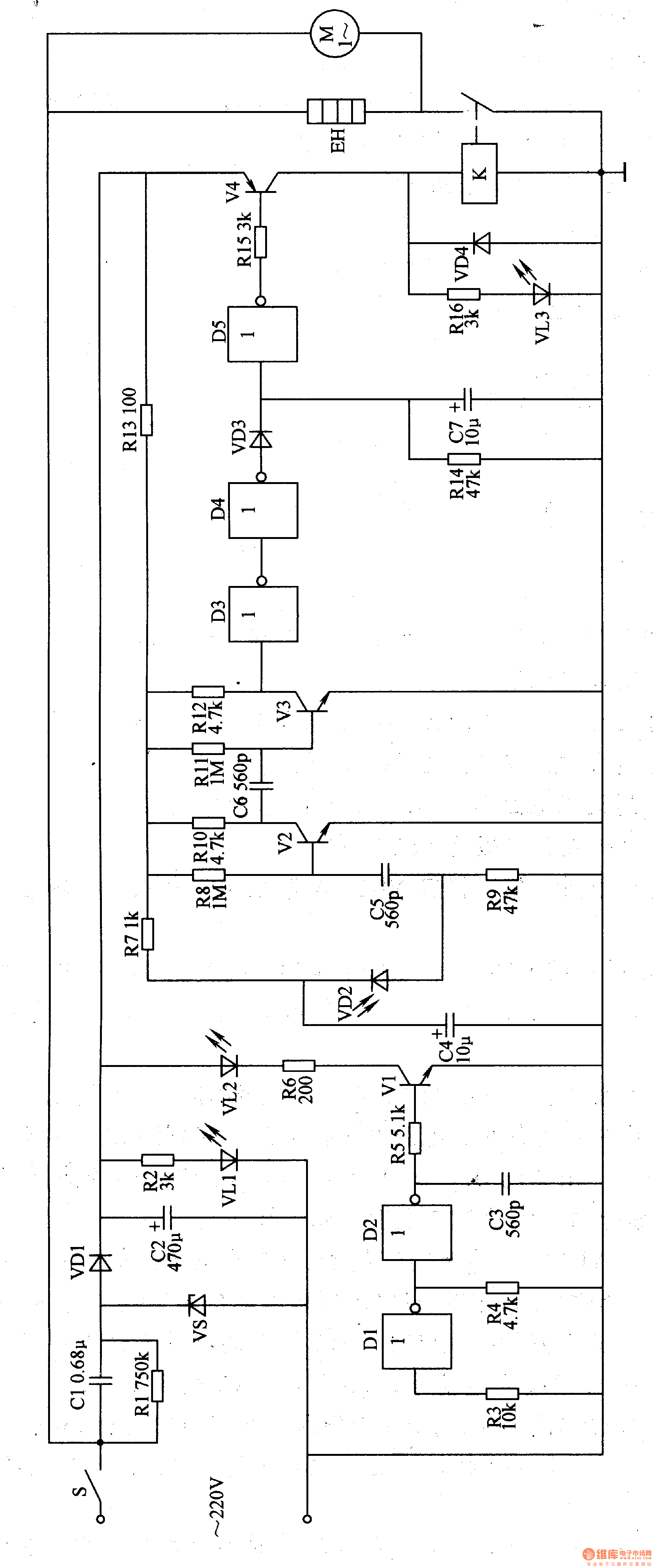
The power circuit is composed of a power switch S, a step-down capacitor C1, a resistor Rl, R2, a Zener diode VS, a rectifier diode VDl, a filter capacitor C2, and a power indicating LED VLl.
The infrared emitting circuit is composed of a non-gate D1, D2, a resistor R3-R6, a capacitor C3, a transistor Vl and an infrared light emitting diode VL2 inside the non-gate integrated circuit IC (D1-D5).
The infrared receiving and amplifying circuit is composed of an infrared photodiode VD2, a resistor R7-R12, a capacitor C4-C6 and transistors V2 and V3.
The delay circuit consists of the internal non-gate D3-D5, diode VD3, resistor R14 and capacitor C7.
The heat fan control circuit is composed of resistors R15, RI6, diode VD4, transistor V4, relay K, fan motor M, and heating wire EH.
Turn on the power switch S, AC 220V voltage after Cl step-down, VS voltage regulation, VDl rectification and C2 filtering, generate DC voltage of about l2V, as the working power of the relevant circuits of the whole machine, and after the R2 current limiting step-down Light up VLl.
After the infrared transmitting circuit is energized, the oscillator composed of the non-gates D1, D2 and R3, R4, C3 oscillates to generate a modulated pulse signal, so that V1 is intermittently turned on, and VL2 is driven to emit modulated infrared light.
In normal times, VD2 does not receive the modulated infrared light emitted by VL2. The positive terminal of C7 is low level, the non-gate D5 outputs high level, so that V4 is cut off, K is in the released state, and the hot air blower (by fan motor M and heating wire EH) Composition) does not work.
When someone puts his hand on the air outlet below the hand dryer, the infrared light emitted by V spit is reflected by the human hand and received by VD2. VD2 converts the infrared light signal into a corresponding electrical signal, and then is amplified by V2 and V3. After the D3 and D4 are processed, the C7 is charged by VD3. When the voltage across C7 is charged to a certain value, the non-gate D5 outputs a low level, so that V4 is saturated, VL3 is lit, and K is energized, which is often When the open contact is turned on, M and EH are energized, and hot air is blown to the human hand to dry it.
When the human hand leaves the air outlet, VD2 does not receive the reflected infrared light and is in a high resistance state. The signal at the output of the non-gate D4 disappears, and C7 discharges through R14, so that the non-gate D5 still outputs a low level, V4, K and M, EH maintains work. When C7 discharge ends (about 3s), D5 outputs a high level, which makes V4 cut off, K is released, its normally open contacts are open, and M and EH stop working.
Component selection
Rl-R16 uses 1/4W metal film resistor or carbon film resistor.
Cl selects a CBB capacitor with a withstand voltage of 450V; C2 selects an aluminum electrolytic capacitor with a withstand voltage of 25V; C3, C5 and C6 select high-frequency ceramic capacitors; C4 and C7 select aluminum electrolytic capacitors with a withstand voltage of 16V. .
VS selects silicon steady voltage diode of lW, l2V.
VLl and VL3 select φ5mm ordinary light-emitting diodes; VL2 selects HG301 type infrared light-emitting diodes.
VDl and VD4 select 1N4007 type silicon rectifier diode for use; VD2 selects RPM-301B type infrared photodiode for use; VD3 selects type 1N4148 type silicon switch diode for use.
Vl selects S9013 type silicon rectifier diode; V2 and V3 select S9014 type silicon NPN transistor; V4 selects S8050 type silicon NPN transistor.
IC selects CD4069 or CC4069, MCl4069 type six non-gate integrated circuits.
K selects JRX-l3F type l2V DC relay (use two sets of normally open contacts in parallel).
EH uses 500-1000W electric furnace wire.
M selects 15-25W AC fan motor.
S selects 10A, 250V power switch.
Wind Generator,Wind Power Generator,Wind Generator Inverter,Portable Wind Generator
Jinan Xinyuhua Energy Technology Co.,Ltd , https://www.xyhenergy.com