When I was in high school, I worked in a local fast food restaurant. At that time, it was not for the purpose of going to college or doing other more practical things, but to buy other things like car stereo.
I have a Toyota Corolla hatchback, which is a broken car and the first perfect car. After two years of accumulation and upgrade, I ended up with a stereo system that was worth more than this car. It is a great and loud system! I have been driving this car for the first two years of my college and working at Texas Instruments. Finally, I eliminated the car and the stereo, but I still have a place in my heart for high-performance car audio.

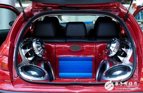
Car body component car audio system (not my set, but similar!)
The main power sources in automotive systems are automotive batteries and alternators. This is a 12V system that provides an alternator operating voltage of around 14.4V. The sound system environment is also very harsh from a voltage transient perspective. To make the window vibrate, you need a lot of power.
Car audio systems have many components: audio mainframes, amplifiers, and equalizers. All of these components require power. In this article, we will focus on the highest power devices - amplifiers. The latest amplifiers use a Class D power stage, which means that the voltage required by the sound system is higher than the voltage of the battery or alternator in the car. In this case, the boost power supply works best. It is not uncommon to be able to output power amplifiers with 500 to 1000W power. For a boost converter with an input voltage of 12V and an output power of 1000W, the input current is close to 100A!
Building a boost converter with an input current of 100A is not easy. To simplify this task, you can choose one of several PowerLab designs and ICs. To handle such a large amount of power, you must use the multiphase method. I have previously written a blog about the advantages of the multiphase approach, which you can read here. For high output voltages and high power levels, not only can non-synchronous solutions be used, but still achieve efficiencies in excess of 90%. The TPS4009x family of controllers can be used in 2, 3 or 4 phase boost designs. In some cases, the synchronization scheme provides better efficiency, but the complexity is slightly higher. The LM5122 is a synchronous boost controller that supports multiphase operation.

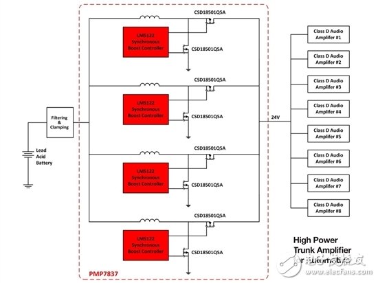
The block diagram is a 4-phase design with four LM5122 devices and eight CSD18501 MOSFETs. This design is the perfect solution for high efficiency automotive audio applications. In PowerLab, you can find not only the design, but also several other designs for automotive audio amplifiers:
PMP2445: TPS40090 + 2x UCC27324 - This design generates 24V from an 8 to 18.5V input at 13A. This is a 4-phase asynchronous boost design.
PMP4538: TPS40090 + 4x UCC27201 - This design generates 28V from an 11 to 18V input at 20A. This is a 4-phase asynchronous boost design.
PMP7837: 4x LM5122 + 8x CSD18501 - This design generates 24V from a 6 to 17V input from a 450W supply. This is a 4-phase synchronous boost design. Synchronous work can achieve efficiencies as high as 96%.
switch and socket, Wall switch and socket, push switch and socket
Guangdong Shunde Langzhi Trading CO., Ltd , https://www.langzhielectrical.com